6 ep1258-000x, 1 ep1258 - introduction, Ep1258 introduction – BECKHOFF EP1xxx User Manual
Page 19
Product overview
2.6
EP1258000x
2.6.1
EP1258 Introduction
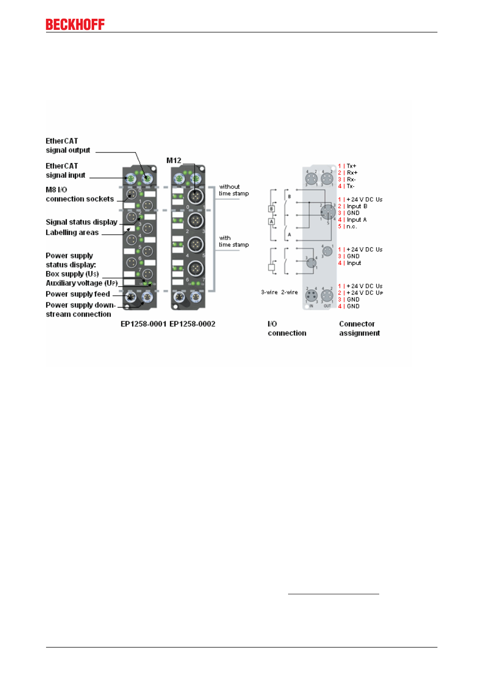
Fig. 10: EP1258
8 digital inputs 24 V
DC
(two channels with time stamp)
The EP1258 EtherCAT Box with digital inputs acquires fast binary control signals from the process level and
transmits them, electrically isolated, to the controller.
The status of the signal is displayed by light emitting diodes; the signal connection is made optionally
through M8 connectors (EP12580001) or M12 connectors (EP12580002). Both modules have 10 µs input
filters.
The sensors are supplied from the control voltage Us. The load voltage Up is not used in the input module,
but may be connected in order to be relayed downstream.
Distributed Clocks
Channels 0 and 1 are assigned a time stamp that shows the time of the last edge change with a resolution of
1 ns. This technology enables signals to be traced exactly over time and synchronized with the clocks
distributed across the system. With this technology, machinewide parallel hardware wiring of digital inputs or
encoder signals for synchronization purposes is often no longer required. As a result, equally timed
reactions, independent of the bus cycle time, are to a large extent possible.
You will find more information about the distributed clocks system in the Distributed Clocks System
Description, which is available under Download
Quick links
Installation
EP1xxx
19
Version 2.1.0