Belshaw Adamatic INSIDER Ventless Donut System User Manual
Page 35
Belshaw Bros., Inc.
• www.belshaw.com • Phone 206-322-5474 • Fax 206-322-5425
Insider TS
MN-1853EN
9
CAUTION
Do not apply Teflon tape to cover or
overlap the pipe opening, as the pipe and
nozzles could become blocked and
prevent the proper flow of agent. Do not
use thread sealant or pipe joint
compound.
All piping shall be securely fastened to pipe
hangers. A union is installed in the discharge
piping close to the cylinder valve, to permit
disconnection and removal for inspection and
service. Dry air or nitrogen should be blown
through the discharge piping to remove chips and
other debris prior to installation of nozzles.
Nozzles shall be installed in accordance with the
limitations described in this manual. Blowoff
caps are provided for each nozzle. These will
prevent dirt and grease from clogging the nozzle.
d) Fusible
Link
Detector
Installation
Fusible links are always used in conjunction with
the Model NMCH Mechanical Control Head.
After mounting the cylinder and control head, the
fusible link line can be installed. The first step
to installing the fusible link line is to install the
detector bracket(s). These brackets must be
installed in the plenum area of the ventilation
hood over all protected Mark II, V, or IX Fryer
and in each duct.
Note: Only FL-212 Fusible Links can be used.
Connect the fusible link brackets together using
1/2” conduit and the conduit connectors supplied
in the detector kit (Model FLK-1/1A). A Pyro-
Chem corner pulley must be used whenever a
change in conduit direction is necessary. The
conduit is connected to the control head through
a knockout in the upper left-side corner.
In general, fusible links centered in the detector
brackets are connected in series using 1/16”
diameter stainless steel cable. The spring plate in
the control head maintains tension on this series
of fusible links.
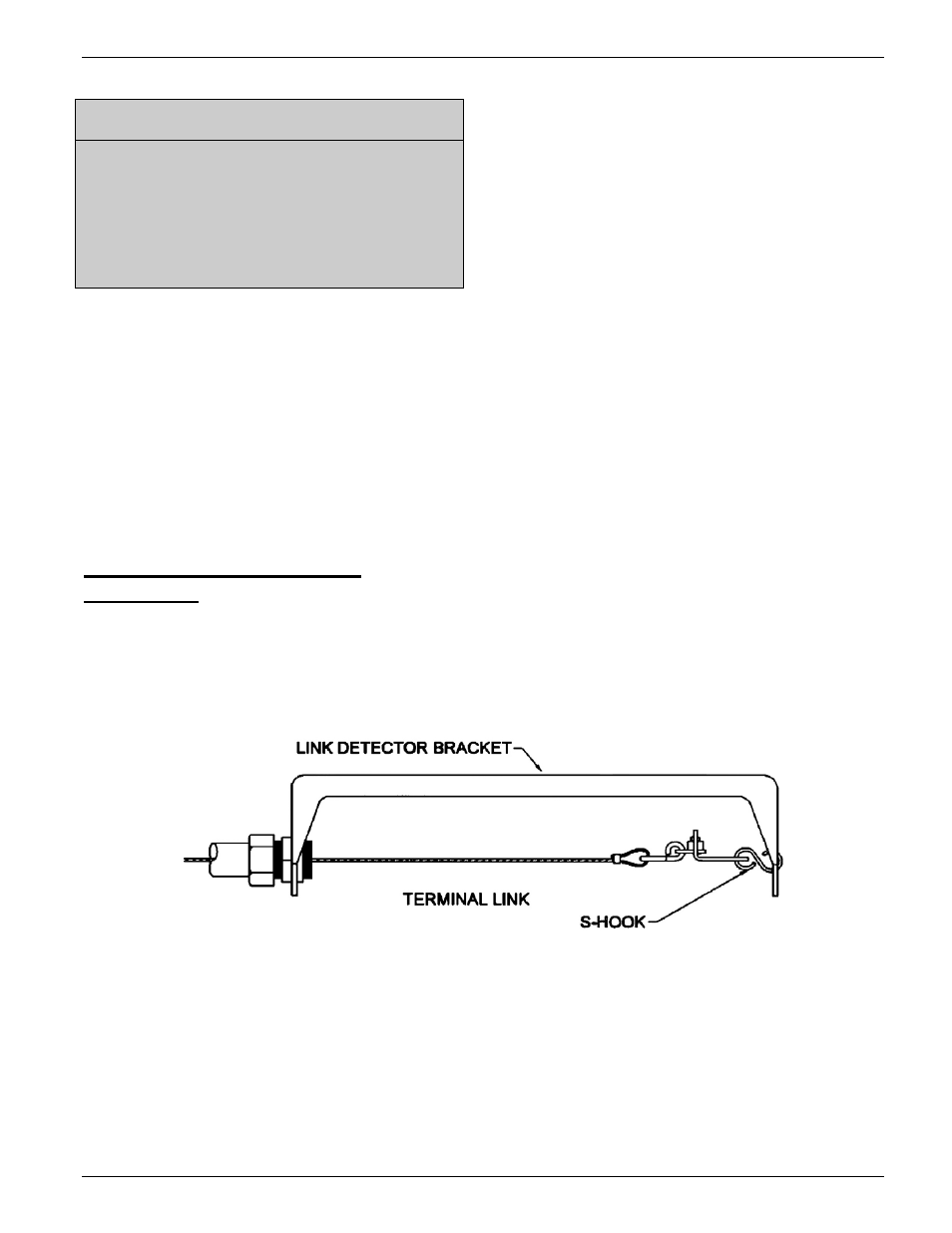
Illustration E
Terminal Link Installation