Belshaw Adamatic INSIDER Ventless Donut System User Manual
Page 36
Belshaw Bros., Inc.
• www.belshaw.com • Phone 206-322-5474 • Fax 206-322-5425
10 MN-1853EN
Insider
TS
If the tension is released for any reason (i.e., a
fusible link separates), the control head will
operate and actuate the system. Maximum
limitations for the fusible link detection line are
as follows:
Fusible links can be installed with or without
fusible link hangers.
1. Fusible Link Installation Without
Hangers
Begin installing links at the terminal bracket.
The link is connected to the far side of the
terminal bracket using an “S” hook. The “S”
hook must be crimped closed after the link is
installed. A tight loop is then made in the cable
and secured by the crimp provided. This loop is
connected to the other side of the terminal link
(see Illustration E) and the cable fed through the
conduit to the next bracket.
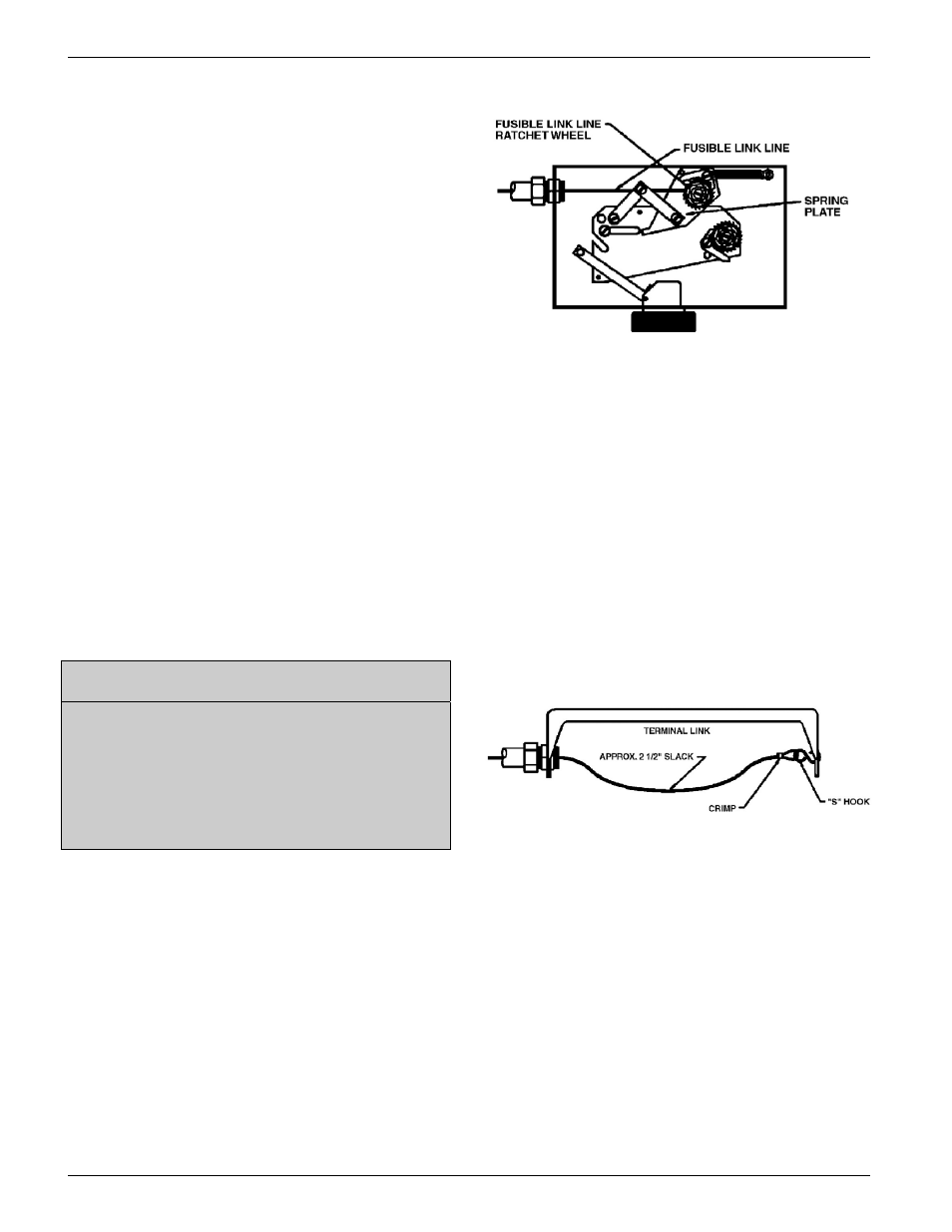
After the last link in the series is connected, the
cable should be fed through the conduit back to
the control head. Thread the cable through the
hole in the fusible link ratchet wheel. The line
must then be crimped, and the crimp positioned
inside the center of the ratchet wheel.
NOTE
Crimps must always be used in
conjunction with two (2) cable lengths.
Loops are the accepted method of
connecting the cable to mechanical
components. The crimp must never be
used on a single cable.
The fusible link line can now be put into a set
position by applying tension to the fusible link
line. This is accomplished by using 3/4” socket
on the fusible link line ratchet wheel. The
ratchet wheel will be ratcheted in a clockwise
direction until the spring plate makes contact
with the top of the control head box. The fusible
link line is now in a set position.
See Illustration F
Illustration F
Fusible Line Link Termination
2. Fusible Link Installation Using Model
FLH-1 Fusible Link Hangers
Beginning at the control head feed the stainless
steel cable through the conduit and brackets to
the terminal bracket in one continuous length.
Allow approximately two and one half (2.5)
inches of slack at each bracket for the installation
of he Fusible Link Hangers. At the terminal link,
a tight loop is made in the cable and secured by
the crimp provided. The cable is attached to the
far side of the terminal bracket using an “S”
hook. The “S” hook must be crimped closed
after the cable is installed. See Illustration G.
Illustration G
Terminal Bracket Connection
Begin installing the Fusible Link Hangers at the
terminal bracket and work toward the control
head. Loop the cable through the oval opening
in the hanger and hook the fusible link on the
loop. See Illustration H
Note: Only FL-212 Fusible Links can be used.