Belshaw Adamatic INSIDER Ventless Donut System User Manual
Page 38
Belshaw Bros., Inc.
• www.belshaw.com • Phone 206-322-5474 • Fax 206-322-5425
12 MN-1853EN
Insider
TS
in the set position, eliminating accidental
actuation during the rest of the installation
procedure. See Illustration K
Illustration K
Miniature Switch Installation
f) Remote
Pull
Station
Installation
The model RPS-M Remote Mechanical Pull
Station is used for remote mechanical actuation
of all system releasing devices. It is to be located
near an exit in the path of egress from the hazard
area no more than five feet above the floor.
NOTE
A Model RPS-M Remote Mechanical Pull
Station must be used for manual
activation of a Model EN-MCU or a Model
NMCH releasing device.
The Pull Station can be surface mounted or flush
mounted. For flush mounting a RACO #232, 4”
deep electrical box or equivalent must be used
(dealer supplied). It is connected to the releasing
device using 3/64” or 1/16” diameter stainless
steel cable. The cable enters the pull station box
through the center hole in the bottom, top, either
side, or the center back hole. The cable enters
the control head through the top center knockout.
The cable must be enclosed in 1/2” conduit with
a Pyro-Chem corner pulley at each change in
conduit direction.
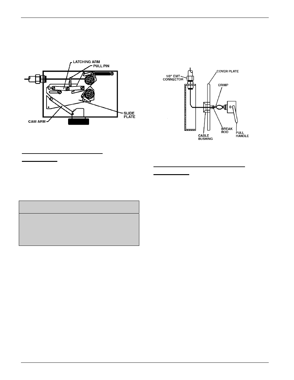
After mounting the pull station box and conduit,
feed the stainless steel cable from the releasing
device, through the conduit, and into the pull
station box. Feed the cable through the bushing
and through the hole provided in the pull handle.
Loop the cable through the pull handle an secure
it with the crimp provided. See Illustration L.
Illustration L
Model RPS-M Remote Pull Station Installation.
g)
System Checkout After
Installation
Model NMCH Mechanical Control Head
Before putting the system into service, all
components must be checked for proper
operation. During this checkout, assure that the
carbon dioxide pilot cartridge is not installed in
the control head actuator. Remove the pull pin
from the hole in the slide plate.
To check satisfactory operation of the control
head, cut the terminal link or the “S” hook
holding the link. This will relieve all tension on
the fusible link line and operate the control head.
The slide plate will have moved fully to the right.
Any auxiliary equipment connected to the dry
contacts of the Miniature Switch in the control
head will have operated.
If any of these events fail to occur, the problem
must be investigated and repaired.
Repair the terminal link and put the fusible link
line back into the set position. This is
accomplished by using a 5/8” socket on the
fusible link line ratchet wheel. The ratchet wheel
will be ratcheted in a clockwise direction until
the spring plate makes contact with the top of the
control head box.