Fitting the mi100166 gooseneck microphone – Cloud Electronics PM12 User Manual
Page 13
PM4/8/12/16 Installation and User Guide v2.2
13
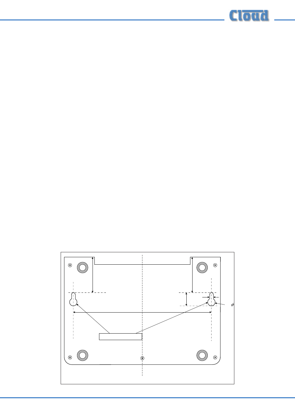
shafts are still visible. Slide the PM over the screwheads using the keyhole slots, so
that the rubber feet act as spacers between the PM baseplate and the wall. If the PM
is not tight against the wall, remove the PM, adjust the length of screw protruding and
try again. Repeat until a good tight fit is obtained. Refer to the illustration below for
drilling instructions.
Fitting the MI100166 gooseneck microphone
The standard gooseneck mic supplied with the PM Series is 300 mm in length, and
this may be inconveniently long if the PM unit is wall-mounted. A 140 mm version,
Part No. MI100166, may be ordered separately from Cloud Electronics, and fitted
instead.
To replace the gooseneck mic, remove the baseplate of the PM unit as detailed on
page 12. It will be seen that the thin twin-and-screen cable from the gooseneck itself
terminates in a screw terminal connector on the right-hand side of the PCB (see
page 32 for location of this connector). (Note that this connector is also used for
the internal chime speaker.) Disconnect the gooseneck by undoing the three relevant
screw terminals on the connector.
The gooseneck itself may now be removed by undoing the 14 mm nut securing it to
the casing – a box spanner is the best tool for this.
Fitting the MI100166 gooseneck assembly is the reverse procedure. Fit the gooseneck
first and tighten the securing nut; then reconnect the twin-and-screen cable to the
connector block, observing the polarities shown on the pcb silk-screening adjacent to
the connector. Then replace the baseplate.
47
47
CL
183
10
5
18
Wall Mounting Holes
All dimensions in mm
PM baseplate drilling details
Not to scale