Cloud Electronics PM12 User Manual
Page 18
PM4/8/12/16 Installation and User Guide v2.2
18
Connecting the PM to a mixer via the analogue interface
In addition to the Digital Paging Interface, the PM incorporates an analogue interface,
permitting the PM to be used with any Cloud (or other) mixer which has an industry-
standard, short-to-ground access port for zone selection.
The connections for the analogue interface are on the internal PCB. Follow the
instructions on page 12
on how to access this. Two cables are required:
Audio Cable: The audio cable should be a standard two-core, screened microphone
cable. This cable should be fed through the rear cable gland labelled AUDIO OUT, and
connected to the screw-terminal block marked TERM8 on the internal PCB. Refer to
page 32
for location of TERM8.
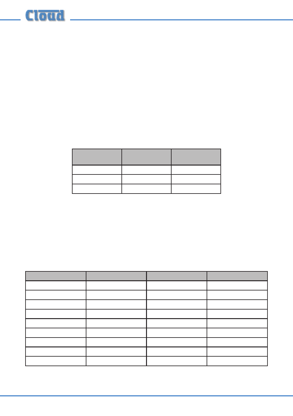
Connect to the terminal block as follows:
Terminal
Use
Typical Cable
Colour
Hot
Phase (+)
Red
Cold
Anti-phase (-)
Black
Gnd
Screen
Screen
Control Cable: The control cable should be a multicore stranded type with an
overall screen. The number of cores required depends on the particular PM model
(PM4, PM8, etc.), and whether DC power is to be derived from the host mixer via the
control cable (see page 19). One core is required for each zone to be connected, plus
a core for the 0 V connection, plus one further core for DC power if needed.
The control cable should be fed through the rear cable gland marked ANALOGUE
PORT, and connected to TERM1, TERM2 and TERM3 as detailed below:
Function
Connect To:
Function
Connect To:
Zone 1 Select
TERM2: Z1
Zone 10 Select
TERM4: Z10
Zone 2 Select
TERM2: Z2
Zone 11 Select
TERM4: Z11
Zone 3 Select
TERM2: Z3
Zone 12 Select
TERM4: Z12
Zone 4 Select
TERM2: Z4
Zone 13 Select
TERM4: Z13
Zone 5 Select
TERM2: Z5
Zone 14 Select
TERM4: Z14
Zone 6 Select
TERM2: Z6
Zone 15 Select
TERM4: Z15
Zone 7 Select
TERM2: Z7
Zone 16 Select
TERM4: Z16
Zone 8 Select
TERM2: Z8
0 V
TERM1: 0 V
Zone 9 Select
TERM4: Z9
+ V
TERM1: + V
Cable core colours will depend on cable type.
Refer to page 32 for locations of TERM1, TERM2 and TERM3.