Cloud Electronics PM12 User Manual
Page 17
PM4/8/12/16 Installation and User Guide v2.2
17
The IN port will only be used if the system is to have more than one PM. To connect
the PM to another PM, connect the OUT port of one to the IN port of the next “in
the chain” using the same wiring standard as shown in the table above. See page 27
for full details.
A system using the Digital Paging Interface should have a total cable length of less
than 1 km.
IMPORTANT: The Digital Paging Interface is a data network, and thus must be
terminated at both ends. In a system comprising a single PM, this means terminations
must be set in both the PM and the host mixer. In systems with multiple PMs, it
means terminations must be set in the PM at the “end” of the chain and the host
mixer. See page 24 of this manual for details of how to set terminations.
NOTE: If the Digital Paging Interface is used as the method of connecting the PM to
the host mixer, the two access glands at the rear of the unit for the audio output and
analogue control cables (see page 9) will not be required.
1
8
1
8
1
8
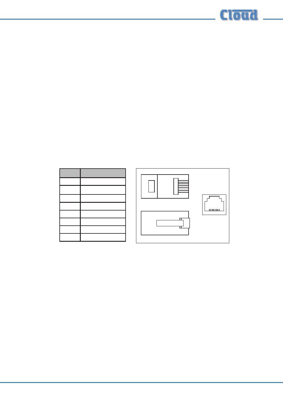
PIN
CAT-5 CORE
1
White + Orange
2
Orange
3
White + Green
4
Blue
5
White + Blue
6
Green
7
White + Brown
8
Brown