Cables and connections – Cloud Electronics PM12 User Manual
Page 16
PM4/8/12/16 Installation and User Guide v2.2
16
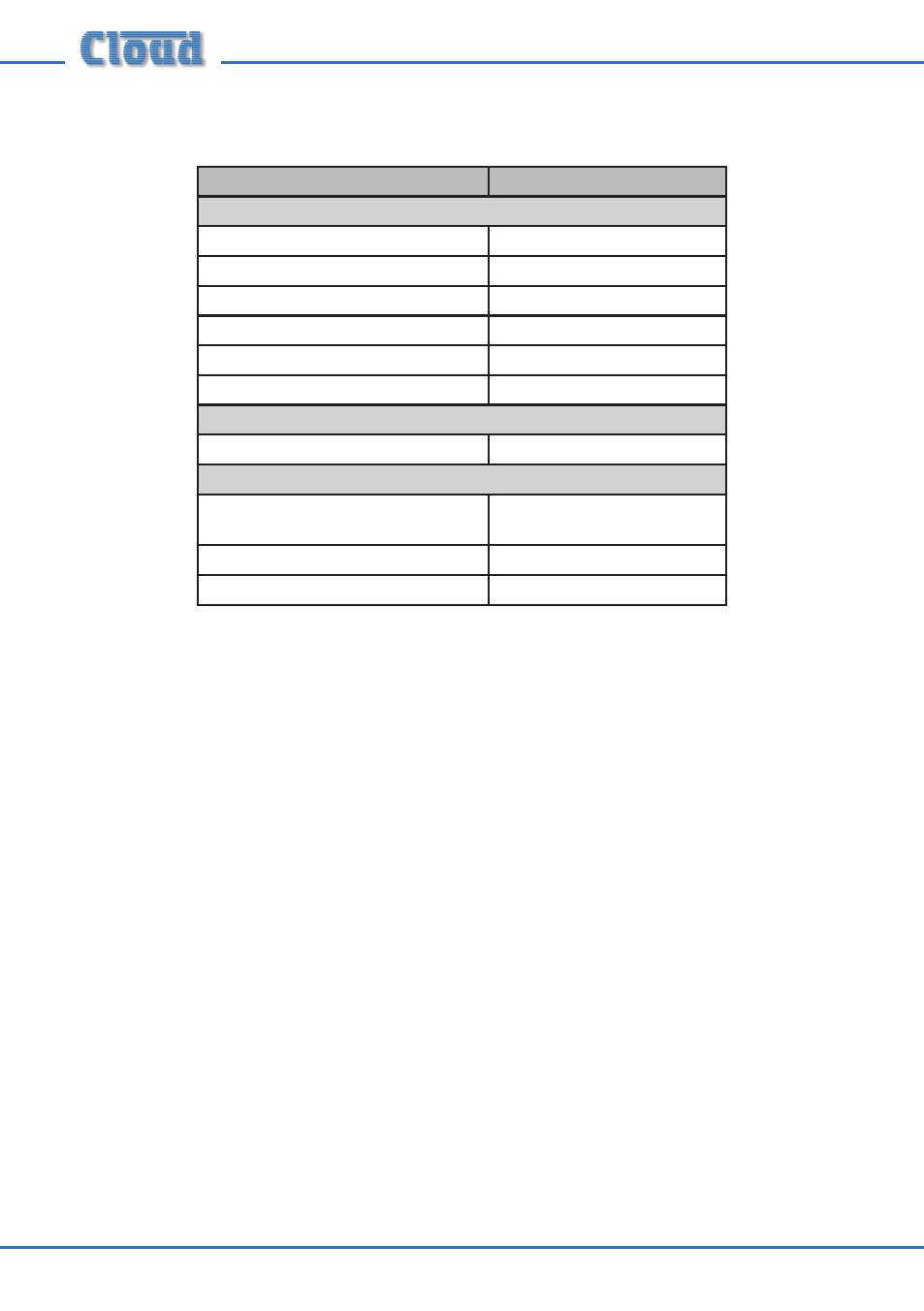
The table below lists the current taken by various Cloud options which may be
installed in the host mixer:
Option
Required Current
Active Remote Plates
LM-1
12 mA
DM-1
18 mA
AE-1
9 mA
BE-1
24 mA
LE-1
22 mA
ME-1
43 mA
DCM-1 Remote Control Plate
CDR-1(F)
50 mA
Bose
®
EQ Modules*
BEQ: M8, M32, MA12, 402, 502A, 802,
MB4, MB24, 502B, 502BEX
12 mA
BEQ: LT3202, LT4402, LT9402, LT9702
17 mA
BEQ: M16
24 mA
The installer should check what options (if any) are fitted, and derate the “Available
Current” figure accordingly before checking if the host has sufficient spare current
capacity to power the PM.
* Note that in the case of the DCM-1, fitting Bose
®
EQ modules does not reduce the current available
from the host.
Cables and Connections
Connecting the PM to a mixer via the digital interface
The rear of the PM is fitted with two RJ45 sockets labelled CAN PORTS. These
constitute the Cloud Digital Paging Interface, which connect the PM to the host
mixer, and/or to other PMs on a network in a multiple-PM system. Where a mixer has
facility for both digital and access contact connection, the digital connection should
be used.
The digital interface carries the microphone audio, paging selection and DC power
on a single RJ45 connector. The audio signal is directional, and is transmitted from the
OUT connector to the IN connector on the next microphone or mixer in the chain.
To connect the PM to a Cloud host mixer via the Digital Paging Interface, connect
the OUT port of the PM to the IN port of the mixer using CAT-5 cable and RJ45
connectors. The cables should be wired pin-to-pin. The standard CAT-5/RJ45 wiring
convention is shown below: