Setting the terminations on the cloud dcm-1 – Cloud Electronics PM12 User Manual
Page 25
PM4/8/12/16 Installation and User Guide v2.2
25
The termination is set in the PM with jumper J4. See page 32 for a diagram showing
jumper locations. The factory default setting is for the termination to be set ON. If
the PM being configured is “mid-chain”, with both its CAN PORT IN and CAN PORT
OUT connectors in use, set the termination to OFF by removing the jumper.
Setting the terminations on the Cloud DCM-1
The Digital Paging Interface is referred to in the DCM-1 documentation as the
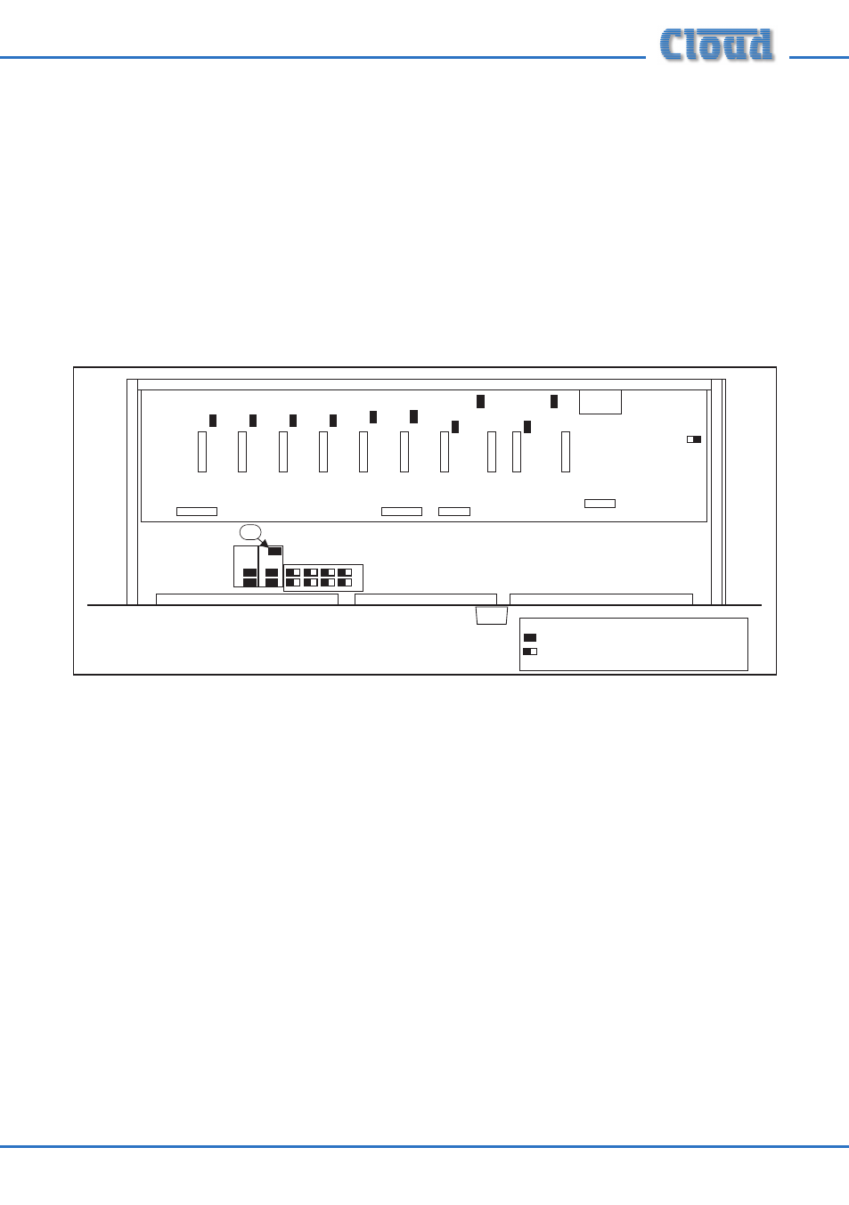
‘CDPM bus’. The termination is set by the DCM-1’s internal jumper J2, and is ON
when J2 is in place. This is the factory default setting, and is unlikely to require
changing. The diagram below shows the jumper’s location.
J2
(UPPER PCB)
(LOWER PCB)
KEY:
Jumper with two possible positions; black
square indicates factory default setting.
Jumper with one position (i.e., present or not)
DCM-1 Jumper Locations
For details of how to set the host mixer’s Digital Paging Interface termination
correctly in other models, please refer to the documentation supplied with the mixer,
or ref.