1 applying ac power – Comtech EF Data CTOG-250 User Manual
Page 61
CTOG-250 Comtech Traffic Optimization Gateway
Revision 1
Back Panel Connections
MN-CTOG250
3–13
3.2.2.1.1
Applying AC Power
A CTOG-250 Standalone (Single Thread) setup uses three individual AC power cords
(two for the CTOG-250 chassis, and one for the CDM-800 unit). A CTOG-250 N:M
Redundant setup uses a 1:3 AC Power Splitter Cord (CEFD P/N PP-0020563 for
North American use, or CEFD P/N PP-0020564 for other regions) for each
configuration in use. Contact Comtech F Data Product Support for further
information.
Sect. 8.6.1 CTOG-250 N:M Redundant Operation in a Vipersat Management System
(VMS)
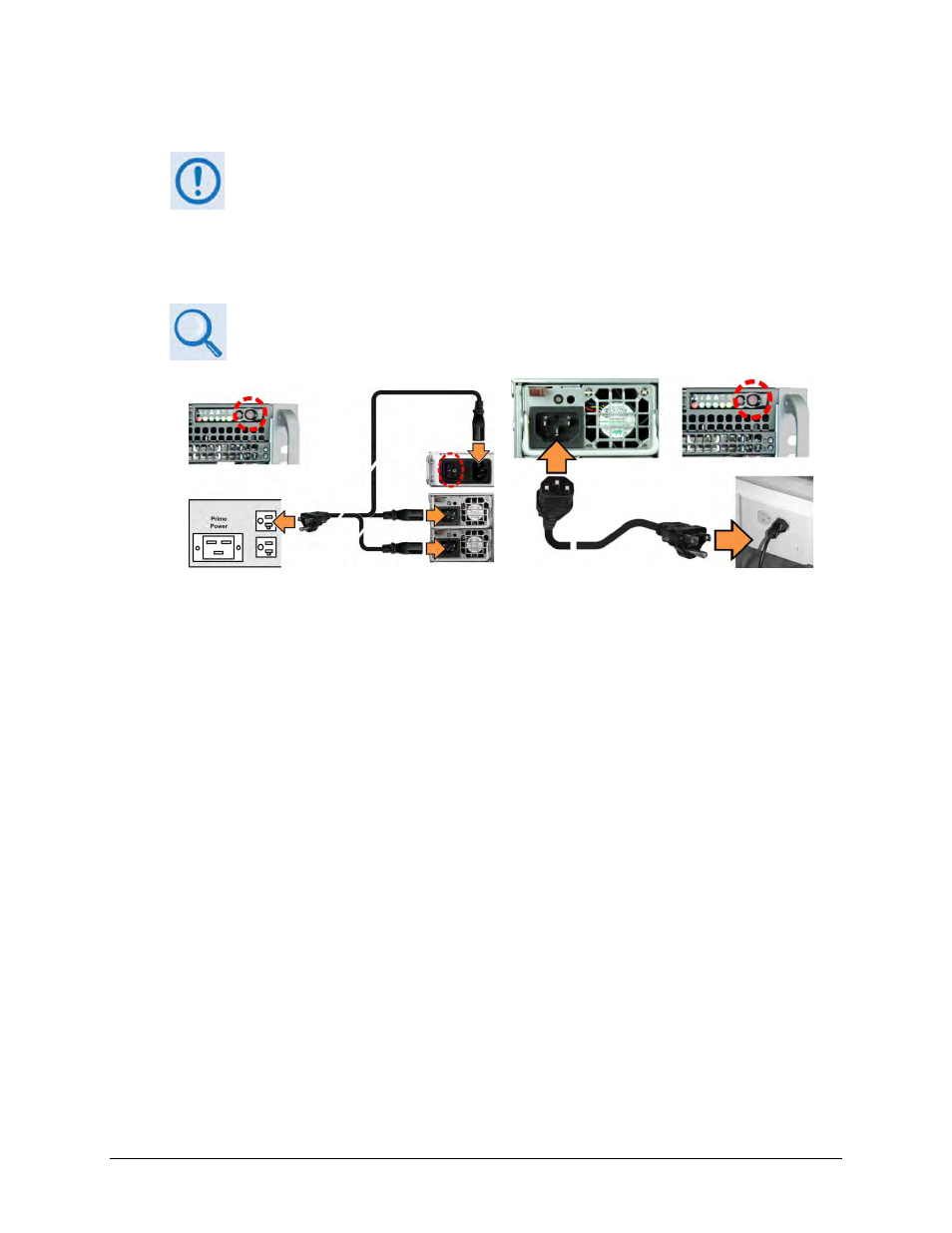
(LEFT) N:M Redundant AC Power application
(RIGHT) Standalone AC Power application
Figure 3-8. Applying AC Power to the CTOG-250
To apply AC power to a CTOG-250 Standalone (Single Thread) setup:
• First, plug the female end of each provided AC power cord into its respective AC
Power Supply Module receptacle.
• Next, plug the male end of each provided AC power cord into a user-supplied AC
power outlet. Each module LED will light amber to indicate the unit is in standby
mode.
• Finally, switch the CTOG-250 ON from the chassis front panel. Each module LED will
light green to indicate power to the unit is ON. The front panel LEDs will also light.
• (Not shown) Connect the AC power source to the CDM-800 as was done for the
CTOG-250, and then switch the CDM-800 ON at the unit rear panel.
To apply AC power to a CTOG-250 N:M Redundant setup (typical for Unit ‘A’ and Unit ‘B’
configurations):
• First, plug a female end of the AC 1:3 power cord into its respective AC Power Supply
Module receptacle and into the CDM-800 AC receptacle.