Comtech EF Data CTOG-250 User Manual
Page 62
CTOG-250 Comtech Traffic Optimization Gateway
Revision 1
Back Panel Connections
MN-CTOG250
3–14
• Next, plug the male end of the AC 1:3 power cord into an outlet in the user-supplied
VMS Network Controller AC Power Bus. Each CTOG-250 AC Power Module LED will
light amber to indicate the unit is in standby mode.
• Finally, switch the redundant setup ON:
o Switch the CTOG-250 ON at the chassis front panel. Each module LED will light
green to indicate power to the unit is ON. The front panel LEDs will also light.
o Switch the CDM-800 ON at the unit rear panel.
3.2.2.1.2
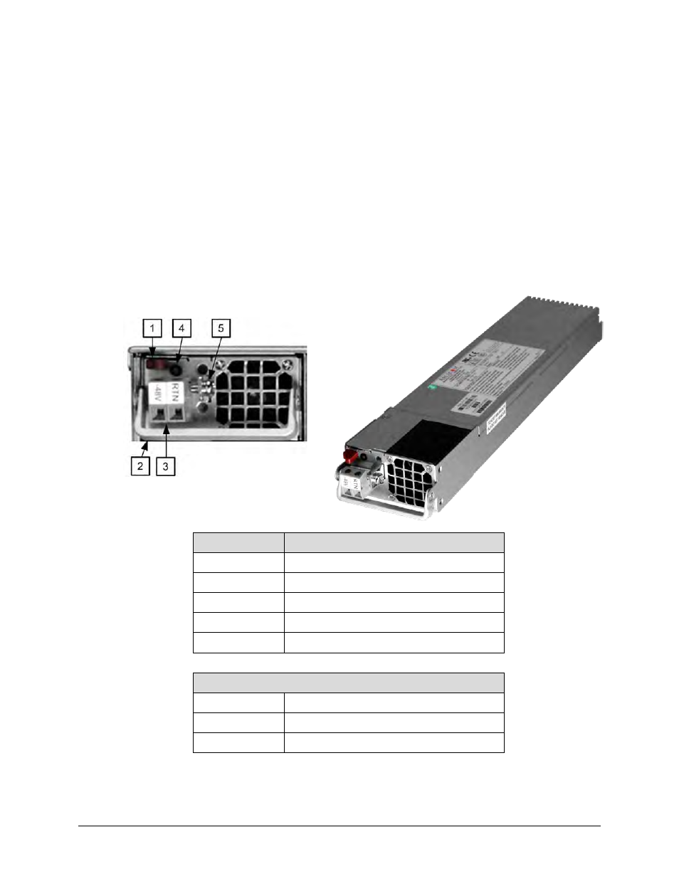
CTOG-250 Typical DC Power and Grounding Interface (Optional)
Feature
Description
1
Module Release Button
2
Module Handle
3
Power Terminal Block
4
Power LED Indicator: Green = Power applied
5
Grounding Bracket
DC Power Specifications
Input Power
TBD
Input Voltage
TBD
Connector Type
Terminal Block
Figure 3-9. Optional CTOG-250 DC Power and Ground Interface