Comtech EF Data CSAT-6070 User Manual
Page 54
5 to 25 Watt Model C-Band Transceiver
Revision 0
Installation
MN/CSAT6070.IOM
2.5.3 C
ONNECT
C
ABLING TO THE
R
EMOTE
S
WITCH
B
OX
, AS/0490
USING
AS/0440 C
ABLE
K
IT
Note: Refer to Figure 2-18a for assembled view, refer to Figure 2-23 for LNA port
locations and refer to Figure 2-13 for Cable kit.
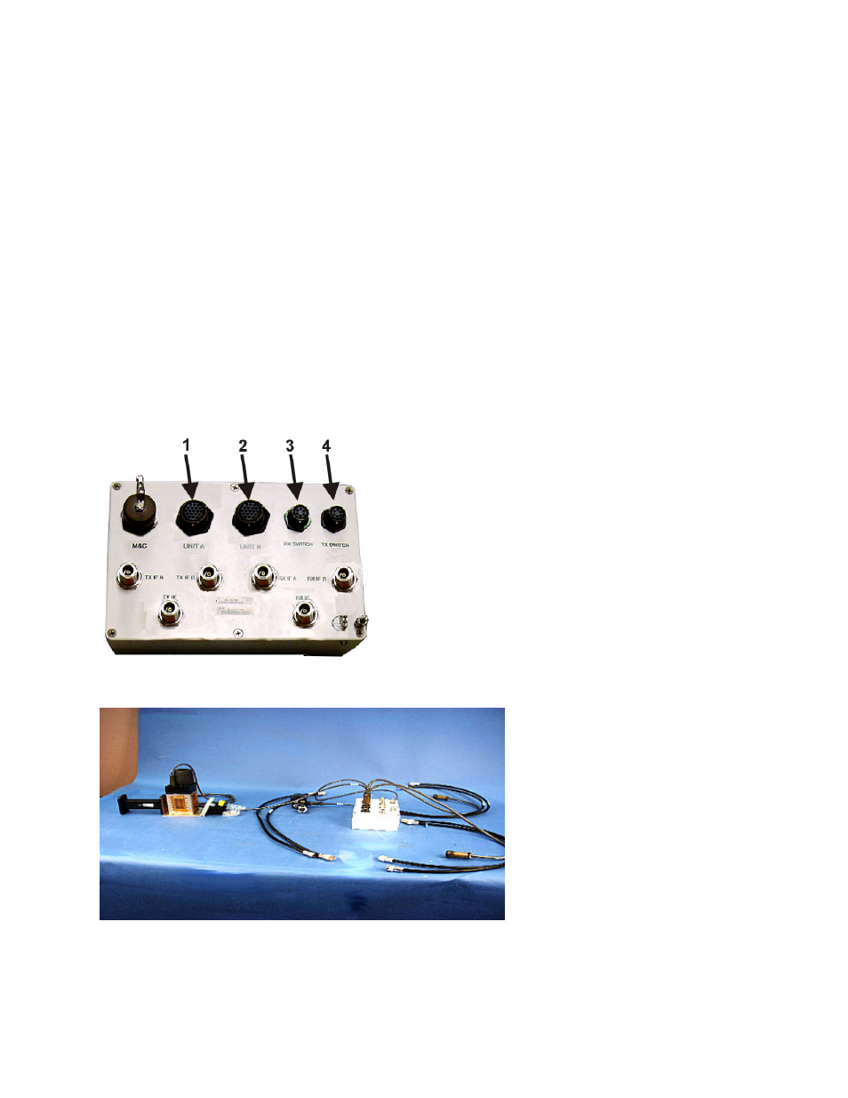
1. Connect one end of the Control cable, (4, Figure 2-12) to UNIT A (1 , Figure 2-17)
connector.
2. Connect one end of the Control cable, (5) to UNIT B (2 , Figure 2-17) connector.
3. Connect one end of Cable (2) to RX SWITCH (3 , Figure 2-17) connector
4. Connect one end of Cable (3, figure 2-13) to TX SWITCH connector (4 , Figure 2-17)
5. Set box aside for later installation.
6. The four RF cables, (1, Figure 2-12) are used to connect the IF ports on the switch
controller to the units.
Figure 2-18.
Remote Switch Cast Box
Figure 2-18a
Switch Box with cables
2–20