Redundancy installation – Comtech EF Data CSAT-6070 User Manual
Page 55
5 to 25 Watt Model C-Band Transceiver
Revision 0
Installation
MN/CSAT6070.IOM
2.5.4 R
EDUNDANCY
I
NSTALLATION
Refer to Figures 2-19, 2-20, 2-21, and 2-22.
Notes:
1. Redundant CSAT’s require two AS/0414 pole mount kits. Refer to Section
2.4.2 for AS/0414 installation instructions.
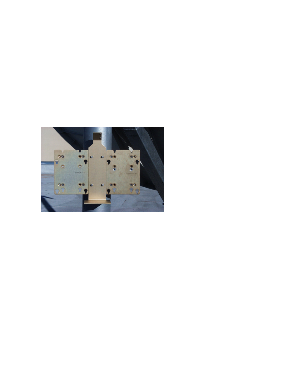
2. After the two pole brackets have been attached to the pole, they need to be
properly spaced in relation to each other. This spacing is established with the
switch-mounting bracket (1, figure 2-11).
Figure 2-19. Installation of the
Redundant Brackets
1. Place two springnuts (7, figure 2-11) in each unistrut bracket (1, Figure 2-1).
2. Center the bracket (1, figure 2-11) horizontally on the top unistrut bracket
(1, figure 2-1) and fasten with two bolts (8, figure 2-11) flat washers (5), and split
washers (6).
3. Loosen lower unistrut bracket and position so the lower holes in the bracket are
aligned vertically with the center of the lower unistrut bracket .
4. Position the springnuts as required. Secure bracket (1, figure 2-11) to the unistrut
bracket (1, figure 2-1) using two bolts (8, figure 2-11), flat washers (5), and split
washers (6). Tighten the tension bracket (2, figure 2-1).
5. Slide two springnuts (5, figure 2-1) into the right-side of each of the two channels of
the unistrut brackets (1, figure 2-1).
6. Place one bracket (1, figure 2-2) against the right side of the switch bracket
(1, figure 2-11).
2–21