Server radio installation, F. d. a – Daktronics Fuelight FL-3000 and FL-4500 Series 36 and 48 Petroleum Price Display and Cash/Credit Display User Manual
Page 24
18
Control Options Setup
• Radios must have direct line of sight between them
• Mount radios away from range-reducing elements (walls, vegetations, etc.) and metal objects
• For best results, mount radios at equal elevation
2. Set the same channel inside both radios.
Server Radio Installation
1. Mount the J-box/signal
converter near a 120
VAC outlet.
2. Mount the server radio
on the outside of the
building within line of
sight of the client radio.
Note: Seal the server
radio with a watertight
grommet where the
cable enters the radio
enclosure.
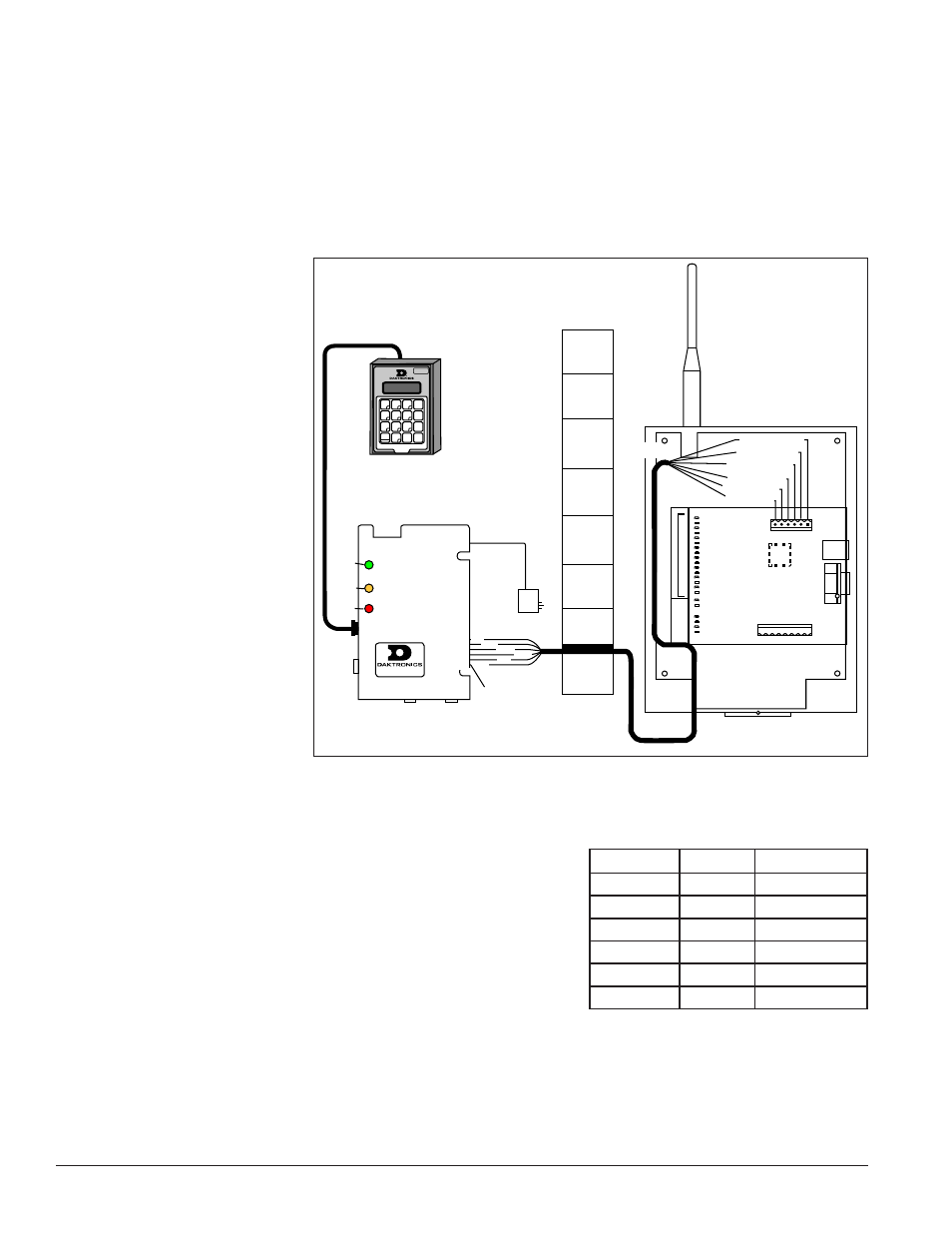
3. Connect power/signal
cables as shown in
Figure 34. The letter for
each step is noted in
a. At the J-box,
connect the
6-conductor, 18
AWG stranded
cable at the terminal
plug labeled RS-422
to Radio.
b. Run the cable from the J-box through conduit to the server radio. The maximum distance from the
J-box to the server radio is 1,000 feet (450 meters).
c. At the server radio, connect the wires to the terminal plug
labeled TB2 (RS-422 IN). The cable is pinned one to one.
Refer to the table.
d. Plug the handheld controller serial cable into the J-box at
the jack labeled DB9 Male DataMaster 100 Connect.
e. Plug the other end of this cable into the handheld controller.
f. Plug the J-box power adapter into a 120 VAC grounded outlet.
GND-N Red
D1IN-N Black
D1IN-P Brown
D1OUT-N White
D1OUT-P Blue
+ VDC-P Green
Server Radio
RS422 IN
C.
Conduit
Building
Wall
Inside
Outside
B.
Red
Black
BrownWhite
Green Blue
GND
422 TX-N
422 TX-P
422 RX-N
422 RX-P
POWER
Green
Amber
Red
12V POWER IN
Pin 1
DB9 Male
DataMaster 100
Connect
J-box/Signal Converter
Power
Adaptor
F.
D.
A.
RS422 T
O RADIO
OR 422 DEVICE
Handheld Controller
E.
Figure 34: Server Radio Connections
J-Box
Wire
Server Radio
POWER
Green
+VDC-P
422 RX-P
Blue
D1OUT-P
422 RX-N
White
D1OUT-N
422 TX-P
Brown
D1IN-P
422 TX-N
Black
D1IN-N
GND
Red
GND-N