Hardware installation serial ports – DFI G5C100-NR User Manual
Page 38
38
2
Hardware Installation
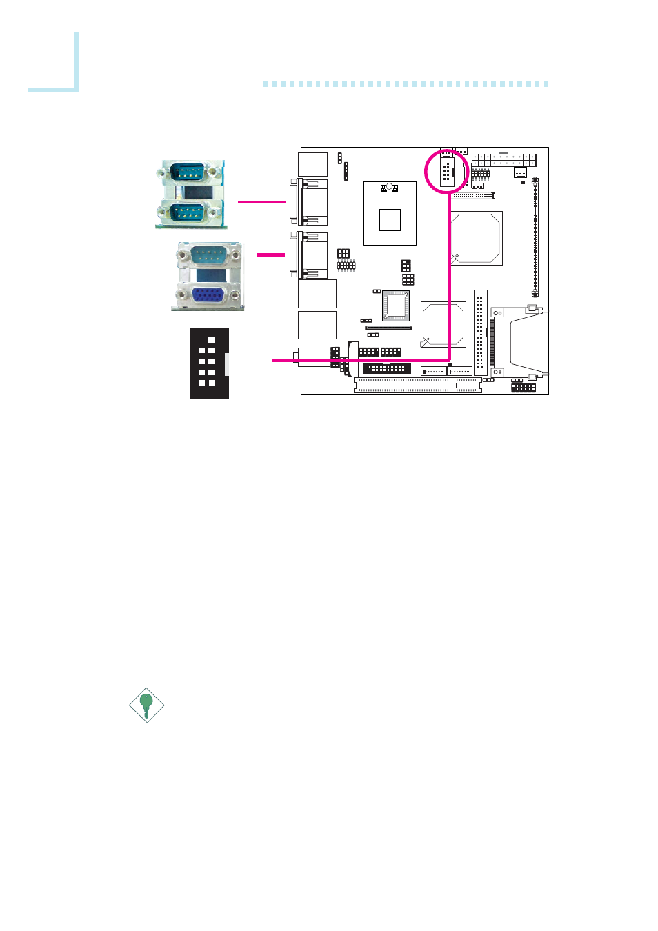
Serial Ports
The system board is equipped with 3 onboard serial ports at loca-
tions CN9 (COM 1 and COM 2) and CN1 (COM 4). It is also
equipped with a 9-pin connector at location J15 (COM 3). The serial
ports are RS-232 and/or RS-485 (COM 4 only) asynchronous com-
munication ports with 16C550A-compatible UARTs that can be
used with modems, serial printers, remote display terminals, and
other serial devices.
To connect COM 3, please refer to the following description. The
serial port may be mounted on a card-edge bracket. Install the card-
edge bracket to an available slot at the rear of the system chassis
then insert the cable connector to J15. Make sure the colored stripe
on the ribbon cable is aligned with pin 1 of J15.
Important:
If the LCD Display Panel that is connected to the LVDS LCD
Panel connector supports touch screen, DO NOT connect a
serial device to COM 3 because the touch screen function is
internally connected to COM 3.
W
COM 4
COM 1
COM 2
W
W
COM 3
2
2
2
2
2 1
1
1
1
1
9
9
9
9
9
DCD-
TD
GND
RTS-
RI-
RD
DTR-
DSR-
CTS-