DR Power Chipper User Manual
Page 11
CONTACT US AT www.DRpower.com 11
3. Connect the two Connectors of the Chipper Harness to the Operator
Presence Connectors (Figure 15).
4. Connect the orange wire of the Chipper Harness to the orange wire coming
from the Mower Switch. If you have a light, connect the other orange wire of
the Chipper Harness to your light.
NOTE: All of the connectors will only fit one way.
Older Field and Brush Mower
1. Disconnect the Operator Presence Connector on the Field and brush Mower
(Figure 16).
2. Connect the two Operator Presence Connectors of the Chipper Harness to
the Operator Presence Connectors of the Field and Brush Mower (Figure
17).
3. Connect the orange wire of the Chipper Harness to the orange wire coming
from the Mower Switch. If you have a light, connect the other orange wire of
the Chipper Harness to your light.
NOTE: All of the connectors will only fit one way.
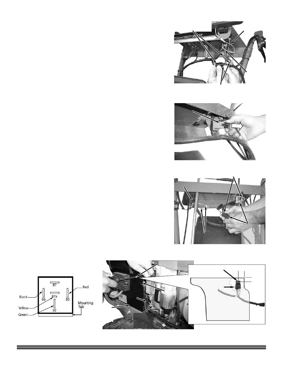
Installing the Relay
1. If there is not a hole already there, Locate and drill a 3/16" hole in the Right
Side Gas Tank Support (Figure 18). Newer Field and Brush Mowers already
have a Relay mounting hole.
2. Route the Relay end of the Harness behind the Gas Tank Support and secure
the Relay to the hole with a 10-24 Screw and Locknut.
3. Connect the black Ground Wire to the Engine Mounting Hardware that is
closest to the Relay area.
4. Refer to Figure 19 for the proper relay color code connections in the event
your relay should become disconnected.
5. Wire Tie the Harness to the Handlebars of the Field and Brush Mower.
3/16" Hole
Figure 18
Relay Mounted
Vertical
Mounting
Screw and
Locknut
Relay
Right Side Gas
Tank Support
1"
1"
Gas
Tank
Support
Ground
Wire
Engine
Mount
Hardware
Figure 17
Existing
Operator
Presence
Connectors
Chipper Harness
Connector Adapters
Light Switch
Connectors
Switch
Operator
Presence
Connector
Figure 16
Older Style
Field and
Brush Mower
Orange
Wire to
Light
Figure 15
Chipper Harness
Connectors
Existing Operator
Presence Connectors
Orange
Wire from
Switch
Figure 19