Specifications, Unpacking the chipper attachment – DR Power Chipper User Manual
Page 7
CONTACT US AT www.DRpower.com 7
Specifications
MECHANICAL
SPECIFICATIONS
Driven by
DR Field and Brush Mower (V-Belt and
Clutch)
Chipping Capacity
3-1/2" Diameter
Number of Chipper Knives
1
Chipper Knife Size
4-1/8" L x 1-1/4" W, 45 deg
Chipper Knife Material
Heat Treated Tool Steel
Adjustable Knife Wear Plate
Yes
Chipper Flywheel
12" Diameter, 1/2" Thick
Flywheel Weight
18 lbs
Chipper Knife Speed
95 mph
Hopper Material
14 GA Steel
Belt Adjustment
Spring Loaded Idler Pulley W/Manual
Engagement
Hopper Opening at Top
8" x 11"
Machine Weight
125 lbs
SHIPPING
SPECIFICATIONS
Shipping Dimensions
24" L x 26" W x 24" H
Shipping Weight
160 lbs
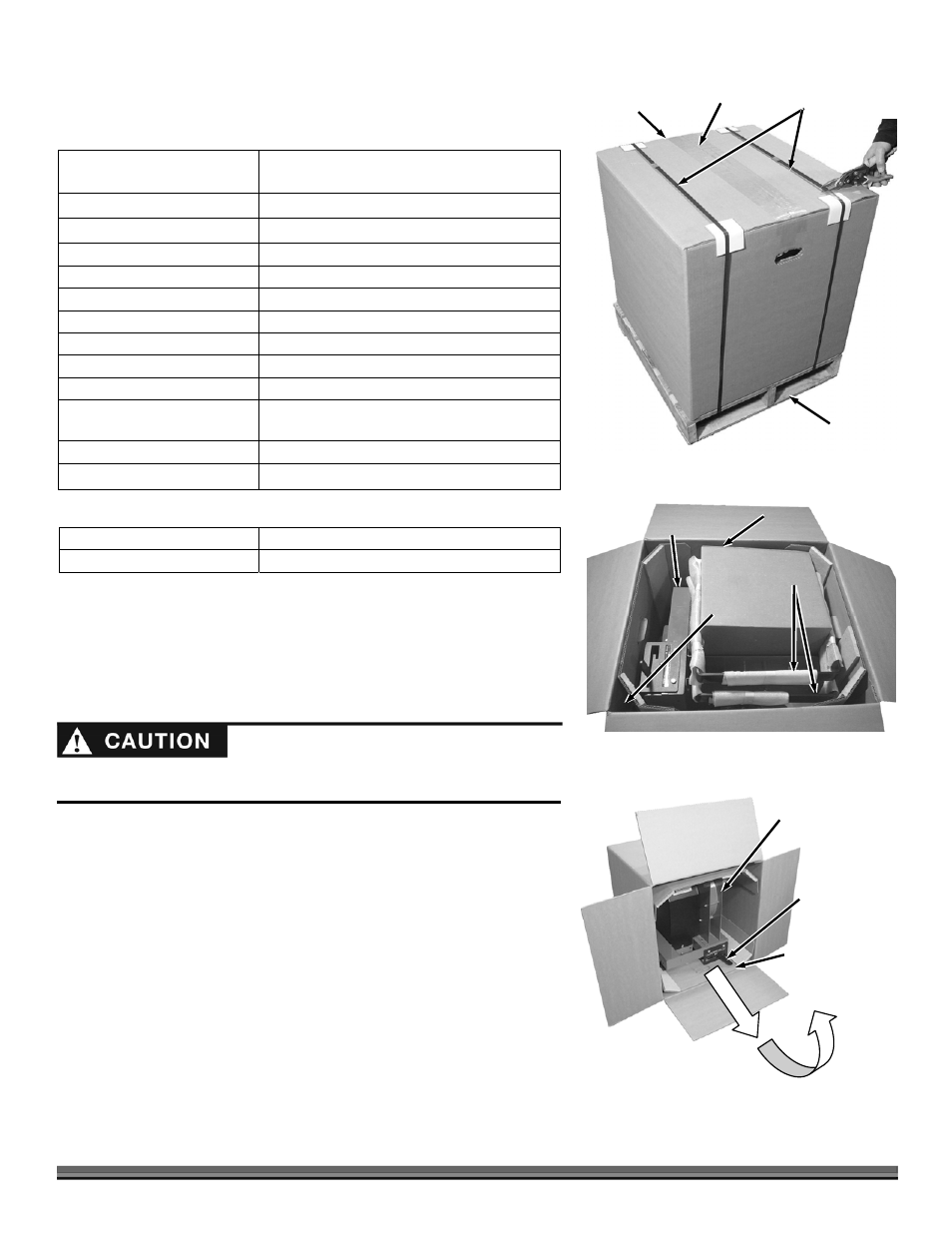
Unpacking The Chipper Attachment
Tools and Supplies Needed:
Wire Cutters
Utility Knife
Safety Goggles
1. Cut the Banding from around the Shipping Box and Pallet (Figure 2).
2. Cut the tape that secures the Box Flaps with a Utility Knife.
3. Open the Box Flaps and remove the Parts Box, Legs and Leg Supports
(standing up in the corner of the Box) (Figure 3).
4. Remove all Foam and Bubble Wrap from the Legs and Supports.
5. Slide the Box off the Pallet and rotate it onto the side so the Chipper Unit
is right side up (Figure 4).
6. Pull the Chipper Unit (with the Corner Supports) out of the Box and then
tip the Chipper Body up so the Belt Release Lever is on top.
Figure 2
Straps
Shipping
Box
Pallet
Tape
Parts
Box
Figure 3
Legs
Leg
Supports
Chipper
Unit
Chipper
Unit
Figure 4
Corner Support
(Frame Side)
Belt Release
Lever
Wear eye protection when cutting the banding. The Banding may be under
tension causing it to snap towards you when it is cut.