DR Power Chipper User Manual
Page 13
CONTACT US AT www.DRpower.com 13
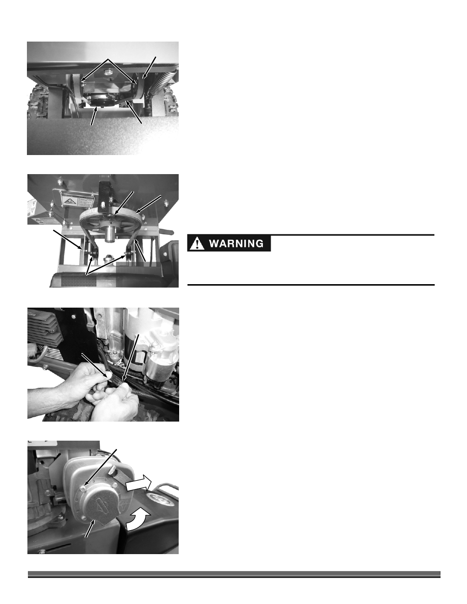
7. Position the Belt onto the Field and Brush Mower Pulley (Figure 24) and
then route it over the two Idler Pulleys and up around the Chipper Pulley
(Figure 25).
NOTE: Ensure that the “V” portion of the Belt rests properly into the Idler Pulleys.
8. Move the Belt Release Lever to the “Tighten” position.
NOTE: There is a slot in each of the bottom Tabs of the Belt Guard. These slots
must slide over the Carriage Bolt Guides that are mounted to the inner Frame
Supports of the Chipper (Figure 20 on previous page).
9. Reinstall the Belt Guard and secure with the Hand Knob.
10. Connect the Wire Harness Connector from the Field and Brush Mower to
the Connector of the Chipper Attachment (Figure 26).
Adjusting the Exhaust Deflector on machines with a Briggs and
Stratton 12.5 hp Engine (serial numbers from ATM123741 to
ATM126369).
Tool Needed:
1/4" Wrench
1. Remove the three Screws that secure the Exhaust Deflector using a 1/4"
Wrench (Figure 27).
2. Rotate the Exhaust deflector so it is facing forward (3 o’clock) and secure in
this position with the three Screws using a 10mm Wrench.
Belt
Figure 24
Chipper Idler
Pulleys
Field and
Brush Mower
Pulley
Twist Belt to
Engage “V”
Properly into
Idler Pulleys
Chipper
Connector
Connector
from
Relay
Figure 26
Belt
Figure 25
Idler Pulleys
Chipper
Sprocket
Twist Belt so “V”
Engages Properly into
Chipper Sprocket
Carriage
Bolt for
belt guard
mounting
(one on
each side)
Before performing this Engine change, stop the engine, wait five (5) minutes
to allow all parts to cool. Disconnect the spark plug wires, keeping them away
from the spark plugs.
Screws
Figure 27
Deflector
Point
Forward