Cord head height adjustment – DR Power 3-Point Hitch (April 2015 - Present) User Manual
Page 12
12
DR
®
3-POINT HITCH TRIMMER/MOWER
Always make sure you remove the screwdriver from the head assembly when
finished. Failure to remove the screwdriver could cause injury when the head
assembly is engaged.
Cord Head Height Adjustment
Note: The Cord Head can be located above or below the Molded Spacer giving you a
1-1/2" range in trimming height. The following steps show moving the Cord Head
from below the Molded Spacer to on top of the Molded Spacer.
Tools and Supplies Needed:
Phillips head Screwdriver with at least a 6" shank
Gloves
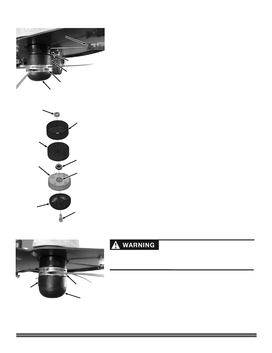
1. Align the hole in the Anti Wrap Canister with the hole in the internal housing
at the location shown (Figure 21).
2. Insert a Philips Head Screwdriver into the hole in the Anti Wrap Canister and
the hole in the internal Housing.
3. Rotate the Mow-Ball
®
Assembly until the Screw Driver slides into a hole in
the shaft, locking it into place.
4. Looking down at the top of the Frame, turn the Mow-Ball
®
clockwise until it
unscrews completely from the Bearing Housing.
Note: If the Mow-Ball
®
continues to turn, but does not come off, check that you
locked the Screwdriver into the shaft. If the Mow-Ball will not turn by hand a 9/16"
Socket can be used on the Bolt (inside the bottom of the Mow-Ball) to loosen it.
You may need to clean grass or debris out of the recess first.
5. Slide the Cord Head, Adapter and Molded Spacer off the Shaft (Figure 22).
6. The Anti-Wrap Can and Spacer should remain on the Shaft with the
Screwdriver.
7. Make sure the Adapter is inserted into the top of the Cord Head as you
install the Cord Head onto the Shaft.
8. Install the Molded Spacer onto the Shaft.
9. Place the head of the Mow-Ball
®
Bolt so it is sitting inside the hex cavity at
the bottom of the Mow-Ball
®
.
10. Looking down at the top of the Frame, hold the Bolt Head in place with your
finger and turn the Mow-Ball
®
counterclockwise to start the Bolt into the Shaft.
11. Tighten the assembly securely by turning the Mow-Ball
®
counterclockwise
when looking down on the top of the Frame (Figure 23).
12. Remove the Screwdriver.
Cord Head
Figure 23
Mow-Ball
®
Molded
Spacer
Mow-Ball
®
Figure 22
Mow-Ball
®
Bolt
Cord Head
Adapter
Molded Spacer
(can be above
or below Cord
Head)
Anti-Wrap Can
Spacer
Adapter Hole
(facing up)
Cord Head
Figure 21
Molded Spacer
Anti-Wrap Can
Mow-Ball
®
Screw Driver