Modifying the pto shaft-if required – DR Power 3-Point Hitch (April 2015 - Present) User Manual
Page 9
CONTACT US AT www.DRpower.com 9
5. Raise the Trimmer up until the Tractor PTO Spline and Trimmer Gearbox Shaft are parallel with each other. Measure from the
end of the Tractor Spline Shaft to the end of the Trimmer Gearbox Shaft and record this dimension in the “SHAFTS LEVEL”
row of the table above.
6. Raise the Trimmer up as far as it will go. Measure from the end of the Tractor Spline Shaft to the end of the Trimmer Gearbox
Shaft and record this dimension in the “FULLY RAISED” row of the table above.
Note: If your longest measurement exceeds 37" you will require a longer PTO Shaft. Do not proceed with installation until you have a
longer PTO Shaft. If you have any questions, please visit us at www.DRpower.com or call 1-800-DR-OWNER (376-9637).
7. Take the shortest recorded measurement you wrote in the table and add 2".
8. Take that number and subtract it from 32" (overall compressed length of the supplied PTO Shaft).
9. This final number is the length that you will need to cut off of the PTO Shaft for it to fit properly to your Tractor.
EXAMPLE: Let’s assume the shortest center-to-center measurement in the table is 27".
27 + 2 = 29 (step 4 above)
32 – 29 = 3 (step 5 above)
You would be required to cut 3" off both halves of the PTO Shaft and 3" off the Guard.
Note: If you end up with 0" or a negative number, then no changes are needed until you reach a maximum long measurement of 37" as
indicated on previous page.
Modifying the PTO Shaft-if required
If you have determined in the previous steps that the PTO Shaft is too long for
your set up, shorten the Shaft as follows:
Tools and Supplies Needed:
Hacksaw
Bench Vise
Tape Measure
File
General purpose Lithium Grease
Note: Your actual PTO Shaft may look different than the one shown in these steps
but the procedures are the same.
1. Separate the PTO Shaft Halves by pulling them apart.
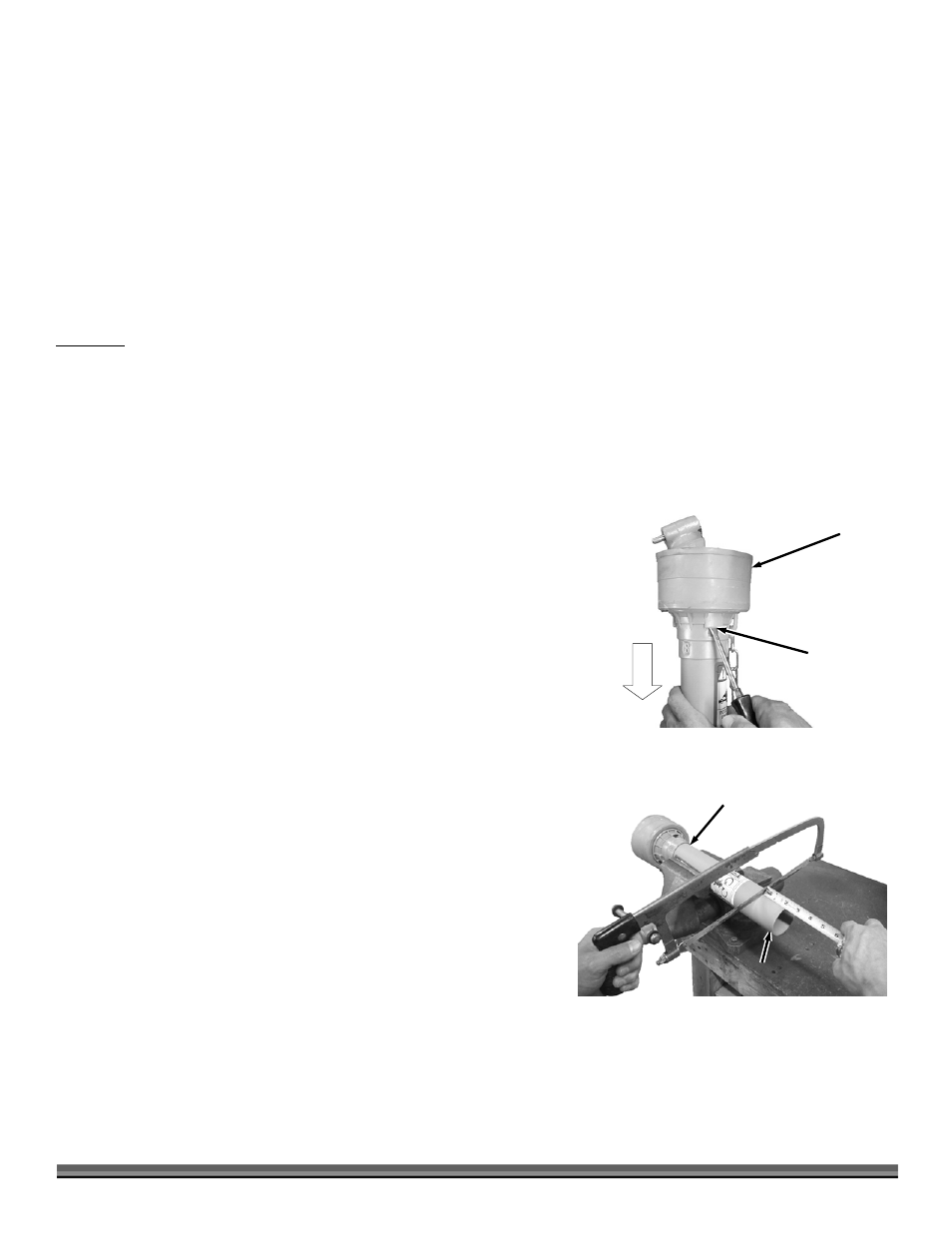
2. Separate the Guards from the PTO Shaft Halves by inserting a flat tip
screwdriver into the Bearing Tab Slots as you pull down on the Safety
Guard to release the Safety Guard from the Shaft (Figure 9).
3. Measure and cut the ends of both Guards the required amount (Figure 10).
Note: If you put the Guards in a vise to hold them, be careful not to clamp it too
tight because it could crack the plastic.
Safety
Guard
Figure 9
Bearing
Tab
Safety
Guard
Figure 10
Cut This
End