Specifications, Attaching the 3-point bracket to the tractor, Attaching the trimmer/mower to the 3-point bracket – DR Power 3-Point Hitch (April 2015 - Present) User Manual
Page 7
CONTACT US AT www.DRpower.com 7
Before performing the following procedure, be sure your tractor engine is off,
brake is set, and the key removed for safety.
Specifications
Tractor Requirements
Category 1, 25 to 45 HP Max.
Drive
Tractor PTO
PTO Speed
540 RPM
Number of Trimmer Cords
4
Belt
6577BR Gates, 134-3/8˝ L
Belt Adjustment
Spring Loaded Idler Pulleys
Max. Wheel Base (distance from outside to outside of
rear wheels)
63"
Cutting Height
3 - 7.5 in (3 - 4.5 on the head + 3 in on the wheel in 1/2" increments)
Cutting Width
22"
Machine Weight
225 Lbs
Attaching the 3-Point Bracket to the Tractor
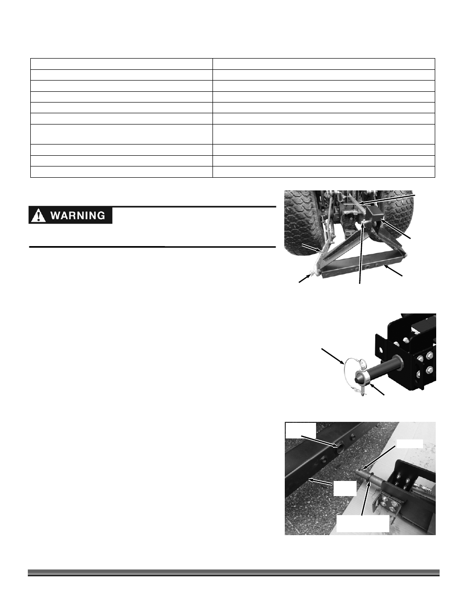
1. Position the 3-Point Bracket at the rear of the Tractor with the Back Plate
facing away from the back of the Tractor (Figure 2). The opposite side of
the 3-Point Bracket facing the Upper Draft Arm is open.
2. Remove the Linch Pin from the top Hitch Pin and remove the Pin from the
3-Point Bracket.
3. Position the Upper Draft Arm inside the top portion of the 3-Point Bracket
and align the Holes.
4. Insert the Top Hitch Pin into the aligned holes and secure with the Linch
Pin.
5. Remove the Hitch Pins from the two lower side mounting Pins of the 3-
Point Bracket. Slide the Lower Draft Arms onto the lower Bracket Pins and
secure with the Hitch Pins.
6. Adjust the Lower Draft Arms as needed to center the 3-Point Bracket and
then lock the Lower Draft Arms to keep them from swinging side to side.
See your Tractor Operator manual for specific instructions to set Draft Arm
position.
Attaching the Trimmer/Mower to the 3-Point Bracket
1. Remove the Hitch Pin with Clip from the Locking Ring and remove the Ring
(Figure 3).
Note: Leave the Pivot Washer on the Pivot Pin. The bevel should be facing the
Trimmer/Mower.
2. Slide the Pivot Pin into the Mounting Hole of the 3-Point Bracket as far as it
will go (Figure 4).
Lower
Hitch Pins
Figure 2
Lower
Draft
Arms
3-Point
Bracket
Back Plate
Upper
Draft
Arm
Upper
Hitch Pin
Mounting
Hole
Figure 4
Pivot Pin
3-Point
Bracket
Pivot Washer
(bevel on this side)
Locking Ring
Figure 3
Hitch Pin and Clip