Installing the wheel assembly, Calculating length of pto shaft needed – DR Power 3-Point Hitch (April 2015 - Present) User Manual
Page 8
8
DR
®
3-POINT HITCH TRIMMER/MOWER
The minimum recommended overlap of the tubes at the center of the PTO
Shaft should be 6". Using a PTO Shaft with less than 6" overlap may fail and
cause machine damage or personal injury.
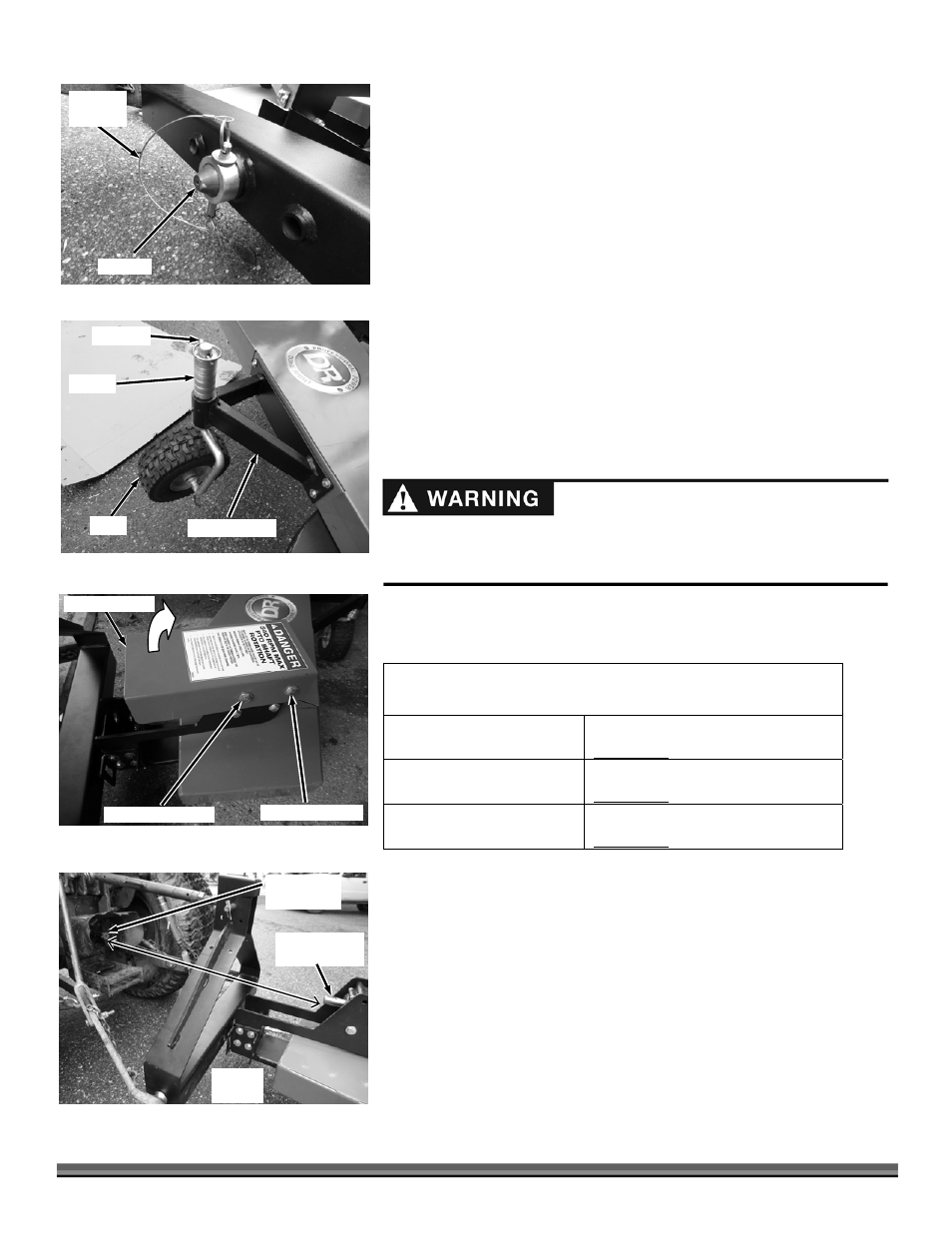
3. Secure the Pivot pin to the 3-Point Bracket with the Locking Ring and Hitch
Pin with Clip (Figure 5).
Installing the Wheel Assembly
1. Remove the Hitch Pin and Spacers from the Wheel Shaft (Figure 6).
2. Insert the Wheel Shaft into the Wheel Support from underneath, install the
Spacers on top and secure with the Hitch Pin.
Note: The Wheel height can be adjusted as needed. This procedure will be
discussed later in Chapter 3 “Operating the DR 3-Point Hitch Trimmer/Mower”
Calculating length of PTO Shaft needed
The PTO Shaft provided with your Trimmer is 32" overall compressed length
and will work “as is” for most applications. Before you install the PTO Shaft it
is good practice to run through the following dimension checks to calculate
optimum PTO Shaft length to determine if modifications are needed.
Without the PTO Shaft installed, use the table below to record the dimensions
as outlined in the following steps.
Tools Needed:
Two 11/16" Wrenches
TRACTOR SPLINE SHAFT TO GEARBOX SHAFT MEASUREMENTS
ON GROUND
Inches
SHAFTS LEVEL
Inches
FULLY RAISED
Inches
Note: Install the Locking Bolt as described in the paragraph “INSTALLING THE
LOCKING BOLT FOR PARALLEL TRIMMING/MOWING” in the “Preparing the
Trimmer/Mower for Trimming” section in Chapter 3.
1. Remove the front Bolt, Washers and Locknut from the Gearbox Guard with
two 11/16" Wrenches (Figure 7).
2. Slightly loosen the rear Bolt, Washers and Locknut of the Gearbox Guard
with two 11/16" Wrenches.
3. Rotate the Gearbox Guard up away from the Gearbox Shaft.
4. Lower the Trimmer all the way to the ground in the operating position
(Figure 8). Measure from the end of the Tractor Spline Shaft to the end of the
Trimmer Gearbox Shaft and record this dimension in the “ON GROUND” row
of the table above.
Gearbox Guard
Figure 7
Remove Hardware
Loosen Hardware
Pivot Pin
Figure 5
Hitch Pin
with Clip
Spacers
Figure 6
Hitch Pin
Wheel
Wheel Support
Tractor
Spline Shaft
Figure 8
Trimmer
Gearbox Shaft
Measure
Distance