DR Power Dual Action 10-Ton Electric (Aug 2011 - Present) User Manual
Page 10
10
DR
®
DUAL-ACTION ELECTRIC LOG SPLITTER
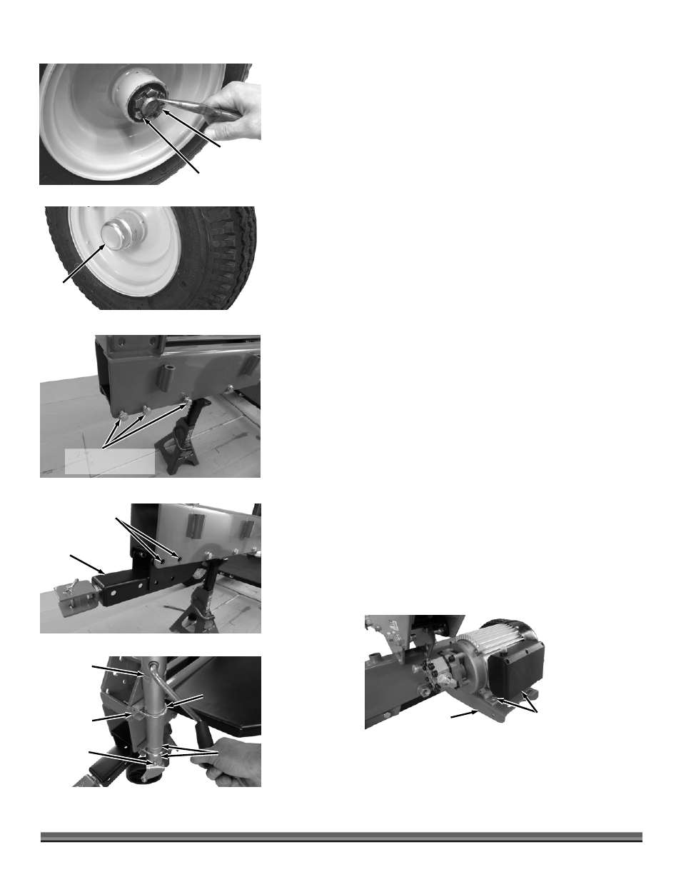
6. Install the Castle Nut onto the Axle Threads with a 1-1/2" Wrench until the
Tapered Bearing is just pushing against the inside of the Wheel Hub but not too
tight (Figure 6). There should be minimal amount of drag on the Wheel when
rotated by hand.
7. Turn the Castle Nut back only as far as needed to align the closest slot in the
Nut with the Hole in the Axle. Insert the Cotter Pin and bend the ends around
with Pliers to secure the Nut. Check that the wheel will rotate freely and does
not wobble on the axle.
8. Install the Dust Cap with a soft face Hammer (Figure 7).
9. Repeat steps 5 thru 8 for the second Wheel.
10. Use a Jack Stand to raise the front of the Splitter allowing room for installing
the Tow Hitch and Jack.
11. Remove the six sets of hardware (three per side) that are installed at the
front of the Beam assembly (Figure 8).
12. Position the Tow Hitch and secure the right side with three sets of the Bolts,
Lock Washers and Locknuts and one set on the left side using two 3/4"
Wrenches (Figure 9).
13. Install the Jack, Spacers and U-Bolts with the lower Clamp and U-Bolt
located between the two positioning rings of the Jack Housing (Figure 10).
Note: The Jack must be installed at a 45° angle for Handle clearance. Temporarily
install a Tray as a guide for checking Handle clearance.
14. Secure the U-Bolts with Flat Washers and Locknuts using a 9/16" Wrench.
15. Remove the Jack Stand and roll the Splitter from the Pallet.
Note: The Slots of the Engine Mount are for Gas Engine mounting and the round
holes are for Electric Motor mounting.
16. Position the Motor onto the Bracket and align the Motor Base holes with the
holes of the Bracket (Figure 11).
17. Install the four sets of Bolts, Flat Washers (top and bottom) and Locknuts to
secure the Motor to the Mount using two 1/2" Wrenches.
Bolts, Washers and
Locknuts (both sides)
Figure 8
Tow Hitch
Assembly
Figure 9
Leave These Out
Jack
Figure 10
U-Bolt
Clamp
Tray
Hitch Pin
Position
Rings
Motor
Hardware
Figure 11
Motor
Mount
Figure 6
Castle
Nut
Cotter Pin
Dust
Cap
Figure 7