DR Power Dual Action 10-Ton Electric (Aug 2011 - Present) User Manual
Page 11
CONTACT US AT www.DRpower.com 11
Figure 16
Control
Lever
Jam Nut
Flat Washer
Note: Remove protective Caps as needed for the following Hydraulic Hose
connections.
18. Install the Elbow Hydraulic Fitting into the Tank assembly by hand until it
cannot be turned any more with your hand. If needed, turn the Elbow back
to align it parallel with the ground and facing out (Figure 12).
19. Tighten the Elbow Jam Nut against the Tank with a 7/8" Wrench.
20. Use Wire Cutters to cut the Cable Ties holding the Hydraulic Hoses
together.
21. Install the Fluid Suction Hose onto the Pump and Tank fittings using a 7/8"
Wrench.
22. Slide the Sheathing over one of the Pressure Hoses and secure it to the
Hose with a Cable Tie near each end (Figure 13).
Note: When installing the following Hose fittings they should be tight, but try not
to over tighten. Start with a snug fit and if leaking is detected then tighten a
bit more until no leaks are detected.
23. Install the Hose with Sheathing to the Control Valve (long elbow end) and
Pump using a 7/8" Wrench.
24. Install the Fluid Return Hose to the Control Valve (long elbow end) and top
of the Tank using a 7/8" Wrench (Figure 14).
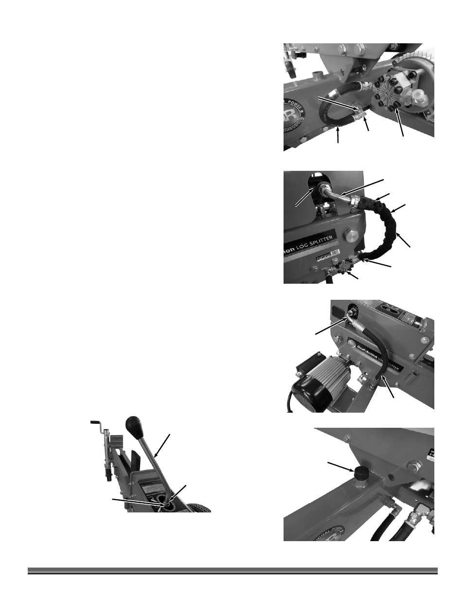
25. Install Hydraulic Cap/Dipstick into the hole on top of the Tank (Figure 15).
26. Remove the Nut and Flat Washer from the Control Lever threads and
reinstall the Nut all the way onto the threads (Figure 16).
27. Place the Washer onto the threads and screw the Control Lever into the top
of the Control Valve as far as it will go. Turn it back to the desired position
depending of your preference to split on the right or left side of the splitter.
Tighten the Jam Nut against the Valve to secure the Lever using a 17mm
Wrench.
28. Install the Trays onto the sides of the Beam assembly and secure with the
Hitch Clips (Figure 17).
Fluid Return
Hose
Figure 14
Long Elbow
Tank
Pump
Pressure
Hose
Figure 13
Sheathing
Long Elbow
Control
Valve
Cable Tie
Cable Tie
Suction Hose
Figure 12
Elbow
Jam Nut
Pump
Hydraulic
Cap/Dipstick
Figure 15