Adding hydraulic fluid – DR Power Dual Action 10-Ton Electric (Aug 2011 - Present) User Manual
Page 12
12
DR
®
DUAL-ACTION ELECTRIC LOG SPLITTER
29. Install the Trays onto the sides of the Beam assembly by aligning the legs
with the receiving tubes and secure with the Hitch Clips (Figure 18).
30. Remove the two left side Bolts, Flat Washers and Locknuts from the Tank
and Axle using two 3/4" Wrenches. Position the Tow Bracket and secure with
the hardware you just removed (Figure 18).
31. Raise the Jack so the Wood Splitter is parallel with the ground.
Adding Hydraulic Fluid
Tools and Supplies Needed:
Paper Towels
Hydraulic Fluid
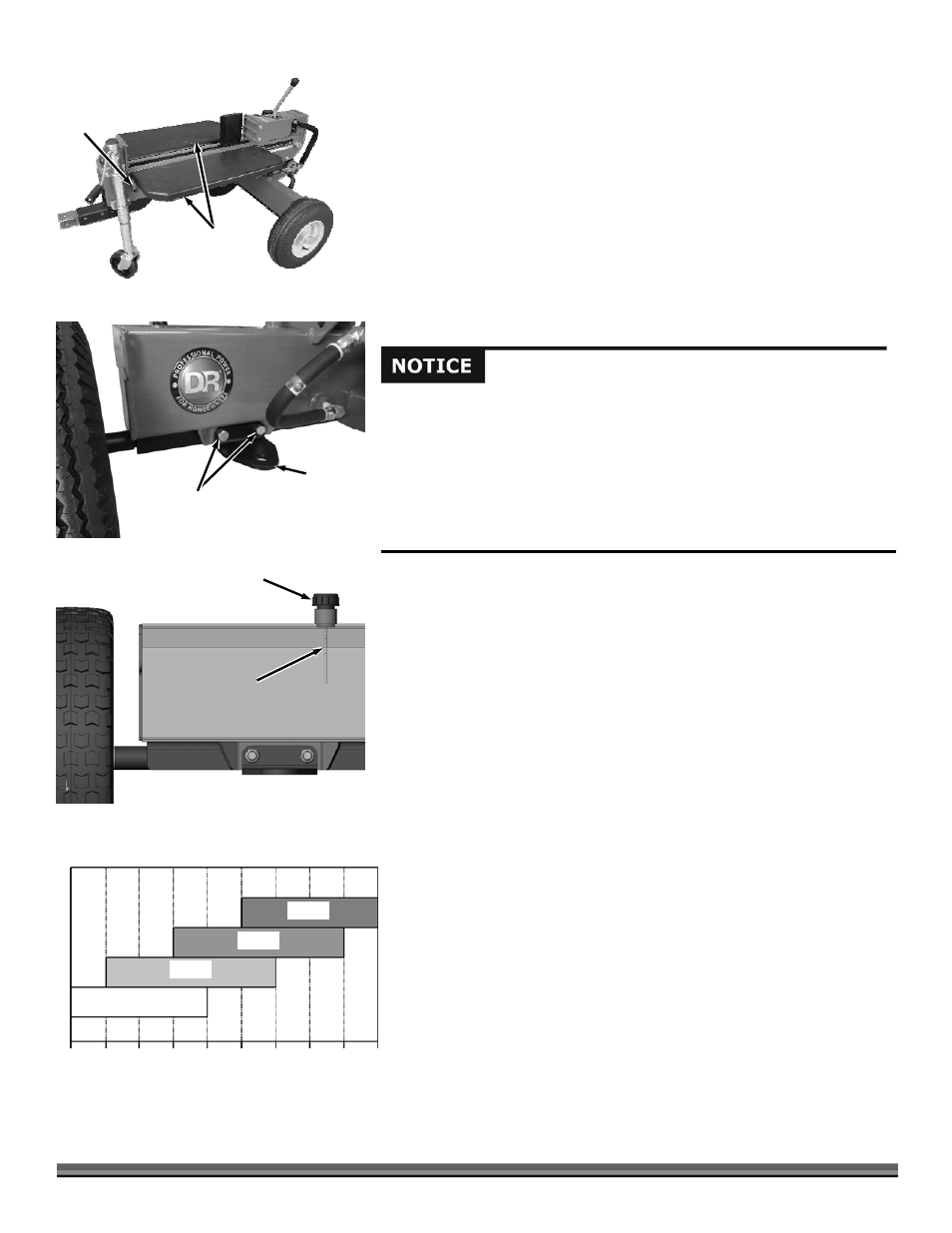
TIP: Check the Fluid level by removing the Hydraulic Fluid Filler Cap and wiping
the steel rod of the Dipstick with a Paper Towel. Reinsert the Cap fully (Figure
19). Remove the Cap and lay the Steel Rod onto a dry Paper Towel and read the
level by the wet mark that is transferred from the Steel Rod to the Paper Towel.
1. Remove the Hydraulic Fluid Fill Cap Dipstick and fill the Hydraulic Tank with
the recommended fluid (see Table-1).
NOTE: The tank is full when the fluid level is within the recommended level on the
Dipstick. The recommended level is in the middle of the two marks on the Steel Rod.
Do not deviate past the marks up or down from that point. If the fluid level is not
within this range, fluid must be added or removed to bring it within that range.
NOTE: The operator should initially only need to add about 5 quarts before
checking the level because some fluid has already been added to the Cylinders.
2. Start the Motor and cycle the cylinder several times (see “Operating
Your DR Dual-Action Log Splitter”, Chapter 3).
3. Retract the cylinder and shut off the Motor and recheck Fluid level.
4. Adjust level as needed.
You must add hydraulic fluid before using the splitter. This machine is
shipped without hydraulic fluid in the hydraulic tank. When performing
the following procedures, fill the hydraulic tank slowly, checking the level
frequently to avoid overfilling.
To get an accurate reading when checking the hydraulic fluid level:
- the machine should be on a level surface.
- the dipstick should be pushed in fully to ensure an accurate fluid level
reading.
Figure 19
Fluid Half
Way on the
Steel Rod
Hydraulic Fluid
Fill Cap
Figure 18
Tow
Bracket
Bolts, Washers
and Locknuts
Trays
Figure 17
Receiving
Tubes
ISO 22
ISO 32
ISO 46
ISO 68
0°
(-18°)
10°
(-12°)
20°
(-7°)
30°
(-1°)
40°
(4°)
50°
(10°)
60°
(16°)
70°
(21°)
80°
(27°)
90°
(32°)
TEMPERATURE FAHRENHEIT (CELSIUS)
HYDRAULIC OIL ISO RECOMMENDATIONS
Table-1