Floscan – Floscan FloNET Standard Flow Model User Manual
Page 13
06/02/2011
4001-443-00B
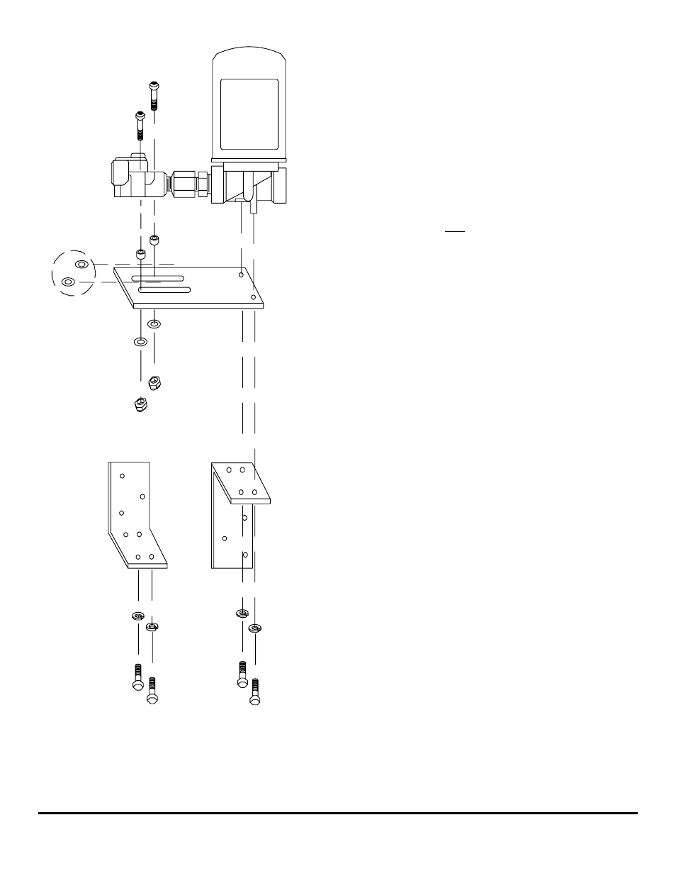
1. Place the Return Sensor-Pulsation Damper assembly, with
inlet and outlet fittings installed, onto the flat bracket.
Orient the Sensor body over the slots and the Pulsation
Damper base over the bolt holes.
FloScan
Additional
Flat Washers
If Needed
OR
Flat Washers
Long Spacers
Lock Washers
2-1/4"
Button Head
Cap Screws
Nylock Nuts
1-1/4"
Hex Head
Bolt
2. Slide a lock washer onto two 1¼” bolts.
3. Chose your 90° mounting bracket option. Assemble the
1¼” bolts through the angle and flat brackets into the
Pulsation Damper base.
4. Tighten the bolts a little past hand tight, compressing the
lock washers slightly.
5. Install the two long spacers between the Sensor body and
flat bracket.
6. Slide the two 2¼” button head cap screws through the
Sensor body, spacers, and flat bracket.
7. Grasp the Pulsation Damper and hold the flat bracket
against the Pulsation Damper’s base. Verify that the
Sensor’s base is perpendicular to the flat bracket.
8. If the Sensor and spacers are flush with the flat bracket,
install flat washers and ESNA nuts onto the 2¼” button
head cap screw ends and tighten until snug. The Pulsation
Damper and Sensor bolts should be tightened evenly.
9. If a small air gap is present between Sensor and spacers,
place one flat washer between each spacer and the flat
bracket.
10. Install flat washers and ESNA nuts onto the bolt ends and
tighten until snug. The Pulsation Damper and Sensor bolts
should be tightened evenly.
(Continued on next page)
FloScan Instrument Company, Inc.
Tel:
(206)
524-6625
Fax:
(206)
523-4961
3016 NE Blakeley Street, Seattle, WA 98105
Email:
Http://www.floscan.com
- N20D-201-2K FloNET N20D-BOS-2K FloNET N20RBBOS-2K FloNET N20D0-2012K FloNET N20D-231-2K FloNET N20D0-BOS2K FloNET N20D0-2312K FloNET N20RB201-2K FloNET N2TD-235-2K FloNET FloNET Hi Capacity Flow Model N2TD-6DB-2K FloNET N20D-3CB-2K FloNET N2TD-6DC-2K FloNET N2TD-6DD-2K FloNET N2TRB6DB-2K FloNET N20RB3CB-2K FloNET N2TD-6CB-2K FloNET N2TRB6CB-2K FloNET N2TD0-6DD2K FloNET N2TD-6ED-2K FloNET N20D-3BB-2K FloNET N20D0-3EE2K FloNET N20D-3DC-2K FloNET N20D0-3BB2K FloNET N20D0-3CB2K FloNET N2TD0-6CB2K FloNET N2TD0-6ED2K FloNET N2TD-6GG-2K FloNET N2TD-6FD-2K FloNET N20D0-3ED2K FloNET N2TD-6CC-2K FloNET N2TD-6FE-2K FloNET N20D0-3DB2K FloNET N2TD0-6FE2K FloNET N2TD0-6BB2K FloNET N2TD-6BB-2K FloNET N2TD-6EE-2K FloNET