Nmea 2000 backbone cable with t-connectors, Pair, Nmea 2000 connector pinout – Floscan FloNET Standard Flow Model User Manual
Page 34
01/04/11
2000-085-00C
POSITION 3:
POSITION B:
R 12664 K-FACTOR
F 5118 PROGRAM
F 19373 PROGRAM
R 47932 K-FACTOR
Temperature K-Factor
Forward Return Forward Return
5. Measure fuel-line length between system components and draw a system sketch.
III. SUPPLY VOLTAGE VERIFICATION
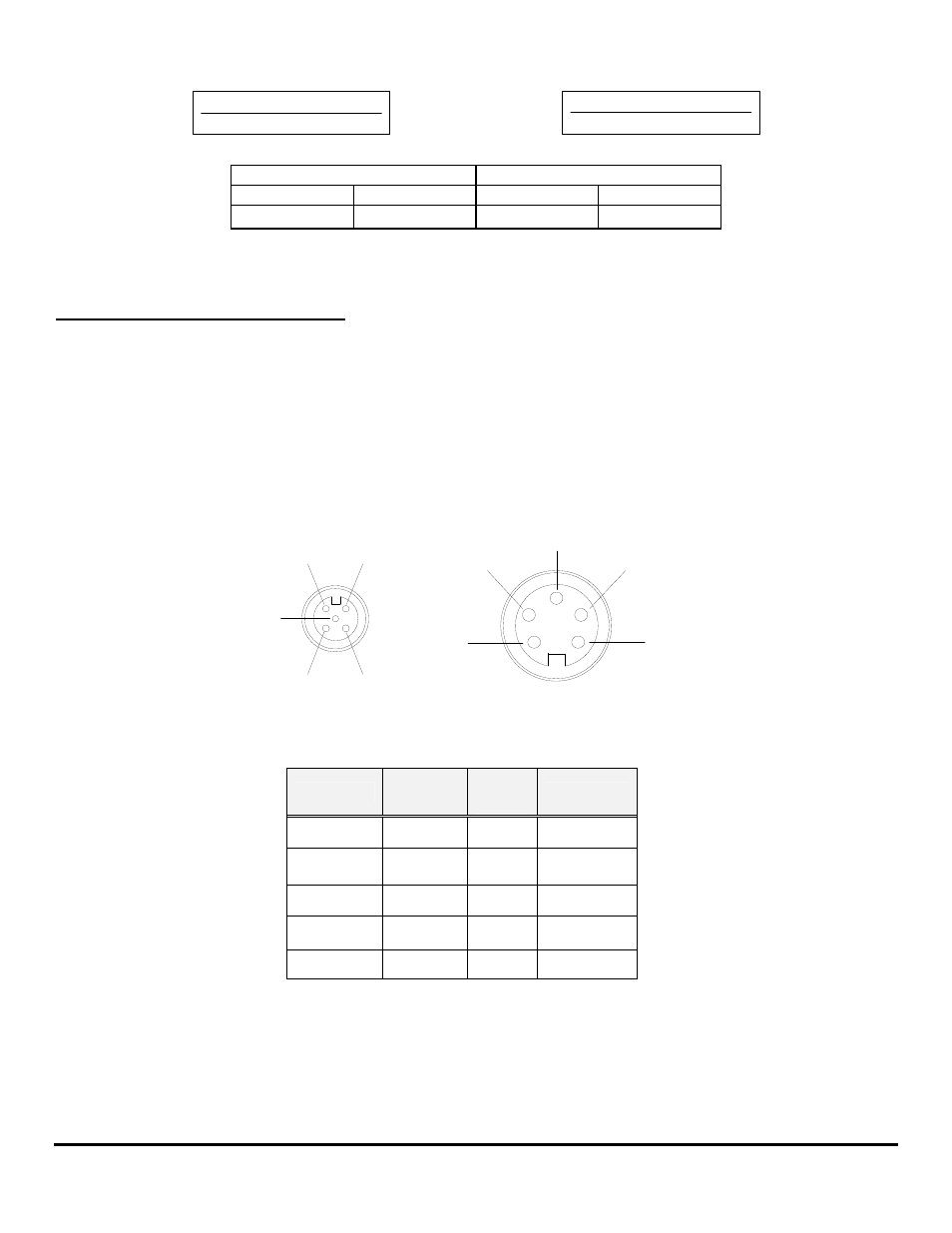
NMEA 2000 Backbone Cable with T-Connectors
1. Referring to the connector pin-out drawing and the table below, disconnect the first connector nearest the Network Power
Connection and measure voltage across the RED and Black Network Power Supply Connection Wires, (NET-S and NET-C pins
or holes). The reading should be approximately 12 to 14 VDC, but not lower than 9 VDC.
Shield (1)
NET-S (2)
NET-L (5)
NET-H (4) NET-C (3)
Shield (1)
NET-S (2)
NET-C (3)
NET-H (4)
NET-L (5)
Micro-C (Female)
Mini-C (Female)
NMEA 2000 Connector Pinout
NAME
COLOR
PAIR
PIN
Shield
Drain 1 Bare
NET-S
Power 2
Red
NET-C
Power 3 Black
NET-H
Signal 4 White
NET-L
Signal 5 Blue
NOTE: Micro-Cable Pin-Out is on the left side of diagram. Mini-Cable Pin-Out is on the right.
2. If 12 VDC is not present, measure between the Red power wire and a known good battery minus point. There may be a loose
battery minus connection or other wiring problem. Check wiring, switches, fuse, and the 12 VDC power source.
3. 12 to 14 VDC is present between the Red wire and battery minus, there may be a loose battery minus connection, broken wire,
open termination or other wiring problem.
FloScan Instrument Company, Inc.
Tel:
(206)
524-6625
Fax:
(206)
523-4961
3016 NE Blakeley Street, Seattle, WA 98105
Email:
Http://www.floscan.com
- N20D-201-2K FloNET N20D-BOS-2K FloNET N20RBBOS-2K FloNET N20D0-2012K FloNET N20D-231-2K FloNET N20D0-BOS2K FloNET N20D0-2312K FloNET N20RB201-2K FloNET N2TD-235-2K FloNET FloNET Hi Capacity Flow Model N2TD-6DB-2K FloNET N20D-3CB-2K FloNET N2TD-6DC-2K FloNET N2TD-6DD-2K FloNET N2TRB6DB-2K FloNET N20RB3CB-2K FloNET N2TD-6CB-2K FloNET N2TRB6CB-2K FloNET N2TD0-6DD2K FloNET N2TD-6ED-2K FloNET N20D-3BB-2K FloNET N20D0-3EE2K FloNET N20D-3DC-2K FloNET N20D0-3BB2K FloNET N20D0-3CB2K FloNET N2TD0-6CB2K FloNET N2TD0-6ED2K FloNET N2TD-6GG-2K FloNET N2TD-6FD-2K FloNET N20D0-3ED2K FloNET N2TD-6CC-2K FloNET N2TD-6FE-2K FloNET N20D0-3DB2K FloNET N2TD0-6FE2K FloNET N2TD0-6BB2K FloNET N2TD-6BB-2K FloNET N2TD-6EE-2K FloNET