Troubleshooting, Flonet interface module, fuel-tron instrument, Flonet interface module – Floscan FloNET Standard Flow Model User Manual
Page 32: Fuel-tron, G p h, Floscan instrument company, inc, Email
01/04/11
2000-085-00C
TROUBLESHOOTING
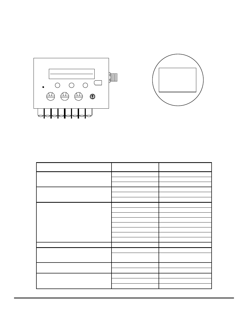
FloNET Interface Module, Fuel-Tron Instrument
BEFORE CALLING FOR ASSISTANCE, COMPLETE THESE TROUBLESHOOTING CHECKS AND RECORD YOUR
FINDINGS. TECHNICAL SUPPORT REQUIRES THIS INFORMATION BEFORE A RETURN AUTHORIZATION WILL BE
ISSUED. IT TAKES ABOUT 20 MINUTES AND IS VERY IMPORTANT IN ANALYZING SYSTEM PROBLEMS.
0
0
FloNET Interface Module
0
4
3
2
1
0
F
E
D
C
B
A
9
5
6
7
8
COVERED
SWITCH
BLUE
ORANGE VIOLET
GREEN
BLACK
RED
RECESSED
ARROW
16.5 GPH
293.7 GAL TOT
COMPUTER
INTERFACE
NMEA 2000
FloScan
Fuel-Tron
16.5
G
P
H
Before starting, please record the FloNET Module and Fuel-Tron Instrument, (if applicable) model number, serial number and switch
settings:
MODEL # _______________________ SERIAL # _________________________
GREEN_______ BLACK_______ RED_______ RECESSED ARROW_______
FAULT
PROBABLE CAUSE
SEE SECTION
Network Power Reversed
Section II
FloScan Instrument Company, Inc.
Tel:
(206)
524-6625
Fax:
(206)
523-4961
3016 NE Blakeley Street, Seattle, WA 98105
Email:
Http://www.floscan.com
Defective NMEA Cable
Section II
Blank FloNET Module Display
Network Power OFF
Section II
Network Power Reversed
Section II
Defective NMEA Cable
Section II
Blank Fuel-Tron Display/No Backlighting
Network Power OFF
Section II
Calibration Calibration
sheet
Incorrect flow sensor(s)
Sensors
Installed backwards
Section VII
Sensors Wired backwards
Wiring Diagram
Incorrect switch settings
Calibration sheet
High or Low Totalizer reading. Over 10%.
Vacuum leak
Section V
Fine Primary Filter
Section VII
Dirty Primary Filter
Section II, Wiring Diagram
Fluctuating GPH Readings
Vacuum leak / Pulsations
Sections IV, V
Wiring Wiring
Diagram
No GPH or Totalizer Readings
Installation sheet, Section
VII
Sensor orientation
Wiring /Instrument failure Sections I, II, III, VII
No Forward or Return Sensor Readings
Sensor Failure
Sections I, II, III
Vacuum Leak
Section V
Incorrect switch settings
Calibration sheet
High Forward or Return Sensor Readings
Sensor orientation
Section VII
- N20D-201-2K FloNET N20D-BOS-2K FloNET N20RBBOS-2K FloNET N20D0-2012K FloNET N20D-231-2K FloNET N20D0-BOS2K FloNET N20D0-2312K FloNET N20RB201-2K FloNET N2TD-235-2K FloNET FloNET Hi Capacity Flow Model N2TD-6DB-2K FloNET N20D-3CB-2K FloNET N2TD-6DC-2K FloNET N2TD-6DD-2K FloNET N2TRB6DB-2K FloNET N20RB3CB-2K FloNET N2TD-6CB-2K FloNET N2TRB6CB-2K FloNET N2TD0-6DD2K FloNET N2TD-6ED-2K FloNET N20D-3BB-2K FloNET N20D0-3EE2K FloNET N20D-3DC-2K FloNET N20D0-3BB2K FloNET N20D0-3CB2K FloNET N2TD0-6CB2K FloNET N2TD0-6ED2K FloNET N2TD-6GG-2K FloNET N2TD-6FD-2K FloNET N20D0-3ED2K FloNET N2TD-6CC-2K FloNET N2TD-6FE-2K FloNET N20D0-3DB2K FloNET N2TD0-6FE2K FloNET N2TD0-6BB2K FloNET N2TD-6BB-2K FloNET N2TD-6EE-2K FloNET