Floscan instrument company, inc, Email – Floscan FloNET Standard Flow Model User Manual
Page 19
03/11/09
2000-082-00A
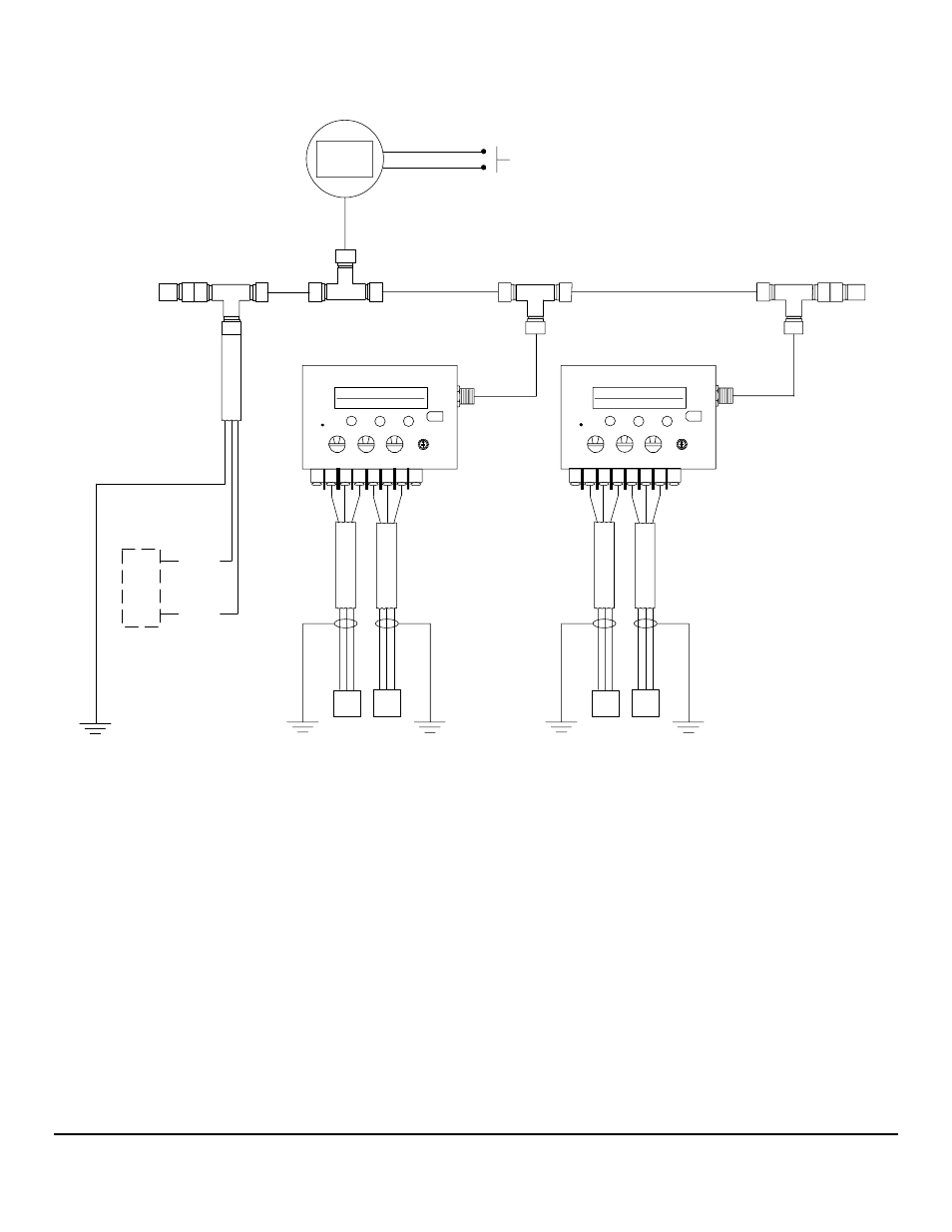
Twin Engine FloNET Interface Module & Fuel-Tron Installation using T-Connectors
0
0
Tap (T-Connector)
Terminating
Resistor
Backbone
Cable
0
4
3
2
1
0
F
E
D
C
B
A
9
5
6
7
8
Flow
Sensor
Forward
Tap (T-Connector)
C
A
B
L
E
RE
D
BL
A
CK
WH
IT
E
Cable Shield
C
A
B
L
E
Cable Shield
Vessel Bonding System
or
Engine Block
Connect Cable Shield
Drain Wire to
Flow
Sensor
Return
RE
D
BL
A
CK
WH
IT
E
Drop Cable
Drop Cable
Vessel Bonding System
or
Engine Block
Connect Cable Shield
Drain Wire to
R
B
W
R
B
W
Tap (T-Connector)
Terminating
Resistor
S4
0
0
Tap (T-Connector)
0
4
3
2
1
0
F
E
D
C
B
A
9
5
6
7
8
Flow
Sensor
Forward
C
A
B
L
E
RE
D
BL
A
CK
WH
IT
E
Cable Shield
C
A
B
L
E
Cable Shield
Vessel Bonding System
or
Engine Block
Connect Cable Shield
Drain Wire to
Flow
Sensor
Return
RE
D
BL
A
CK
WH
IT
E
Drop Cable
Vessel Bonding System
or
Engine Block
Connect Cable Shield
Drain Wire to
R
B
W
R
B
W
S4
NMEA 2000
FloScan
Fuel-Tron
Network Power
Supply Connection
16.5
16.8
P
S
G
P
H
PORT
STBD
16.5 GPH
293.7 GAL TOT
16.8 GPH
305.4 GAL TOT
SPST
Momentary ON
Switch
FloNET Interface Module
FloNET Interface Module
+12VDC
-12VDC
Vessel Bonding System
or
Engine Block
Connect Cable Shield
Drain Wire to
Shield
Electronic
Distribution
Panel In
Accordance
With
ABYC E-11
FloScan Instrument Company, Inc.
Tel:
(206)
524-6625
Fax:
(206)
523-4961
3016 NE Blakeley Street, Seattle, WA 98105
Email:
Http://www.floscan.com
- N20D-201-2K FloNET N20D-BOS-2K FloNET N20RBBOS-2K FloNET N20D0-2012K FloNET N20D-231-2K FloNET N20D0-BOS2K FloNET N20D0-2312K FloNET N20RB201-2K FloNET N2TD-235-2K FloNET FloNET Hi Capacity Flow Model N2TD-6DB-2K FloNET N20D-3CB-2K FloNET N2TD-6DC-2K FloNET N2TD-6DD-2K FloNET N2TRB6DB-2K FloNET N20RB3CB-2K FloNET N2TD-6CB-2K FloNET N2TRB6CB-2K FloNET N2TD0-6DD2K FloNET N2TD-6ED-2K FloNET N20D-3BB-2K FloNET N20D0-3EE2K FloNET N20D-3DC-2K FloNET N20D0-3BB2K FloNET N20D0-3CB2K FloNET N2TD0-6CB2K FloNET N2TD0-6ED2K FloNET N2TD-6GG-2K FloNET N2TD-6FD-2K FloNET N20D0-3ED2K FloNET N2TD-6CC-2K FloNET N2TD-6FE-2K FloNET N20D0-3DB2K FloNET N2TD0-6FE2K FloNET N2TD0-6BB2K FloNET N2TD-6BB-2K FloNET N2TD-6EE-2K FloNET