Floscan FloNET Standard Flow Model User Manual
Page 15
06/02/2011
4001-443-00B
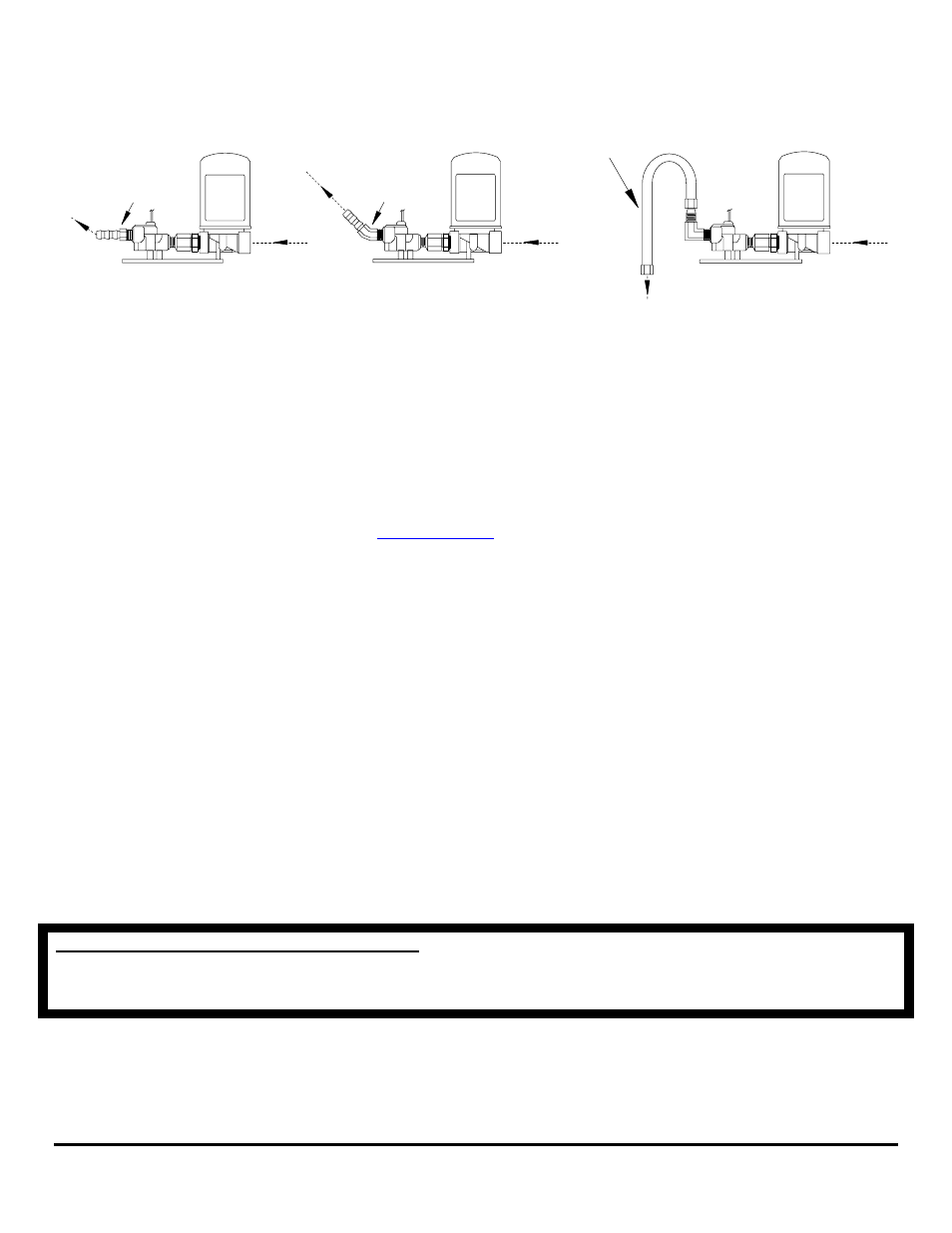
9. If possible, install the Return Sensor – Pulsation Damper assembly at a low point in the fuel system.
Return Sensor
And Pulsation
Damper Assembly
FloScan
45-Degree
Elbow Fitting
Return Sensor
And Pulsation
Damper Assembly
FloScan
Straight
Fitting
Return Sensor
And Pulsation
Damper Assembly
FloScan
3/8" JIC
Tube Assembly
(PART #231-058-00)
10. There must be some vertical rise to the return fuel flow upon exiting the Return Sensor. There should be a minimum, “Up-Hill”
climb of 1 or 2 inches. Higher rises up to 3 feet or a little more are ok.
11. If installing the Return Sensor-Pulsation Damper as outlined in step 9 is not practical, please refer to steps 12 and 13 below.
12. If the return line is fairly horizontal but with a small, “Down-Hill” drop after exiting the sensor, install an upward pointing 45°
elbow into the return sensors outlet port. Install the fuel line with a downward radius bend. Do not pinch the hose.
13. If there is a steep vertical drop in the return fuel line, a tube with a 180° radius bend may be the best option. This option requires:
• One, 90° male elbow with one male JIC 37° 3/8” or Dash 6 (–6) end, and one 1/4" male NPT end.
FloScan Instrument Company, Inc.
Tel:
(206)
524-6625
Fax:
(206)
523-4961
3016 NE Blakeley Street, Seattle, WA 98105
Email:
Http://www.floscan.com
• Two, Dash 6 (–6), (3/8) FlareTite fitting
be installed onto the male JIC fitting ends).
• One, Dash 6 (–6), (3/8) JIC tube assembly.
The tube assembly, P/N 231-058-00 can be purchased directly from FloScan Technical Support. The 90° NMPT x JIC elbow fitting,
and the FlareTite fitting seals can be purchased at most hydraulic shops.
14. Flow sensor model numbers are molded into the colored plastic wire cap. Sensors are shipped in matched pairs. They must not be
mixed on twin engine installations. Match codes are identified by a single stand-alone letter stamped into the sensor body, or
from a colored sticker on the sensors body.
15. Model *235 sensors are temperature compensated and stamped with their instruments serial number, xxxxF (Forward), xxxxR
(Return). *235-2K Temp-Comp sensor kits are precisely calibrated and matched to each instrument. Sensors are labeled
FORWARD and RETURN and must be installed in these positions for proper operation. The instrument head serial number
must match the flow sensor(s) serial number.
16. If there is a shut-off valve in the return line, do not operate the engine with the valve closed. If the engine is run with the valve
closed, fuel return line pressure could exceed the FloScan Return Sensor pressure rating of 100 PSI.
NOTE: Minimize the number of 90º elbows and pipe fittings on the sensor or pulsation dampers inlet port. Excessive use may
create a high vacuum, fuel restricting, pressure drop across the forward part of the fuel system. Refer to the engine owners’
manual for maximum fuel pump inlet vacuum. A vacuum gauge can be used to confirm that the system is within limits.
CAUTION, DO NOT OVER TIGHTEN FITTINGS. Over-tightening may crack the sensor’s body or pulsation damper’s
base. Cracks cause leaks, and fuel leaks sometimes cause catastrophic explosions and fire. Assemble fittings with a Lubricating,
Fuel Proof, Non or Semi Hardening pipe thread sealant designed for aluminum and stainless steel threads, (Loctite 567 or equivalent).
DO NOT USE TEFLON TAPE.
- N20D-201-2K FloNET N20D-BOS-2K FloNET N20RBBOS-2K FloNET N20D0-2012K FloNET N20D-231-2K FloNET N20D0-BOS2K FloNET N20D0-2312K FloNET N20RB201-2K FloNET N2TD-235-2K FloNET FloNET Hi Capacity Flow Model N2TD-6DB-2K FloNET N20D-3CB-2K FloNET N2TD-6DC-2K FloNET N2TD-6DD-2K FloNET N2TRB6DB-2K FloNET N20RB3CB-2K FloNET N2TD-6CB-2K FloNET N2TRB6CB-2K FloNET N2TD0-6DD2K FloNET N2TD-6ED-2K FloNET N20D-3BB-2K FloNET N20D0-3EE2K FloNET N20D-3DC-2K FloNET N20D0-3BB2K FloNET N20D0-3CB2K FloNET N2TD0-6CB2K FloNET N2TD0-6ED2K FloNET N2TD-6GG-2K FloNET N2TD-6FD-2K FloNET N20D0-3ED2K FloNET N2TD-6CC-2K FloNET N2TD-6FE-2K FloNET N20D0-3DB2K FloNET N2TD0-6FE2K FloNET N2TD0-6BB2K FloNET N2TD-6BB-2K FloNET N2TD-6EE-2K FloNET