Floscan FloNET Standard Flow Model User Manual
Page 27
03/16/09
2000-086-00A
PART II: Propulsion Engine Systems
Idle Consumption Adjustment for Forward and Return, Two Sensor Propulsion Engine Systems
• Start and run engine(s) until it is at operating temperature.
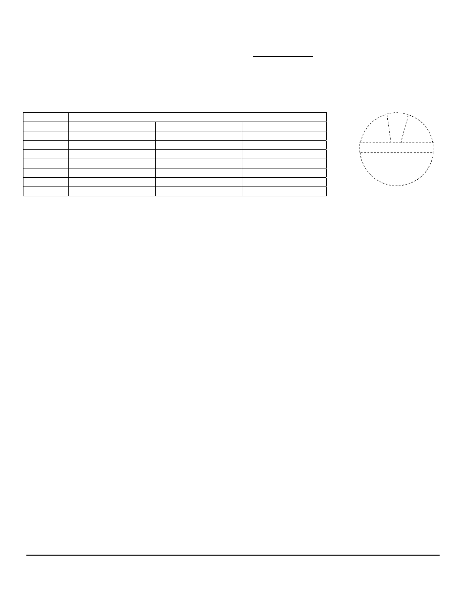
• Referring to the switch diagram, rotate the Red and Black switches to position “0”.
• Increase engine speed to 1800 RPM for one minute. This purges any trapped air from the system.
• Return engine speed to low idle and determine its’ consumption from Table 1 below.
1
0
F
E
D
C
B
A
9
6
7
8
5
4
3
2
0%
+2%
+4%
+6%
+8%
+10%
-2%
-4%
-6%
-8%
-10%
-12%
-14%
-16%
-18%
+12%
RED Switch
FloScan Instrument Company, Inc.
Tel:
(206)
524-6625
Fax:
(206)
523-4961
3016 NE Blakeley Street, Seattle, WA 98105
Email:
Http://www.floscan.com
Table 1
No Load Idle Consumption
HP Non-Turbo
w/
Turbo
Gasoline
100-400
0.1-0.5 GPH, (1-2 LPH)
0.3-0.7 GPH, (2-3 LPH)
.5-1.2 GPH, (2-5 LPH)
400-750
0.8 GPH, (3 LPH)
1.0 GPH, (3-4 LPH)
1.2-1.8 GPH, (5-7 LPH)
750-1000
1.0 GPH, (4 LPH)
1.5 GPH, (5-6 LPH)
1.8-2.5 GPH, (7-9 LPH)
1000-1250
2.0 GPH, (7-8 LPH)
2.5 GPH, (9-10 LPH)
---
1250-1500
3.0 GPH, (11-12 LPH)
3.5 GPH, (13-14 LPH)
---
1500-2000
3.5 GPH, (13-14 LPH)
4.0 GPH, (15-16 LPH)
---
2000-3000
4.5 GPH, (17 LPH)
5.0 GPH, (18-19 LPH)
---
• Rotate the Red Switch until the idle GPH or LPH reading matches engine HP from Table 1.
NOTE: At this point idle consumption is approximate. It establishes operating parameters for final calibration.
Part III: Determining Optimum Tank Configuration & Cruise RPM
• Determine the optimum fuel tank configuration for your vessel. If possible, single engine vessels should draw and return fuel to a
single tank. On twin engine vessels, try to configure the fuel system so that each engine draws and returns fuel to its’ own
dedicated tank. If your twin engine vessel has only a single tank, equal consumption rates for both engines must be assumed.
• Close any cross-connect or limber line valves between tanks during calibration.
• Take your vessel for a short cruise. Using the GPH or LPH reading as a guide, determine the best cruising RPM for the way you
normally operate. Don’t be concerned that the readings are slightly off. Calibration is most accurate when done at a single
cruising RPM.
Part IV: Final Calibration
• Return to the fuel dock and top off the fuel tank(s).
• Reset the totalizer so that the Interface Hub totalizer reading is zero.
• Operate the generator under load, or take the vessel for a cruise. Once underway steam at your optimal cruising RPM,
(Determined in Part III). Consume a minimum of 20 to 30 gallons, (75 to 115 liters) of fuel per engine. Higher consumption gives
better accuracy.
• After consuming some fuel, return to the fuel dock and top off the fuel tank(s).
• Compare the FloNET totalizer reading to the fuel pump reading.
• Calculate the percentage difference between the fuel pump & FloNET totalizer readings. Refer to Examples I & II below.
• Determine if the FloNET totalizer is reading High or Low.
• Rotate the Black Switch until the Interface Hub totalizer reading matches the fuel pump reading.
• Starting at “0”, rotating the BLACK Switch in a clockwise direction increases the totalizer readings by 2% for each click.
• Rotating the switch in a counter-clockwise direction decreases totalizer readings by 2%.
• Totalizer readings can be increased by 10%, or reduced by 20%.
Single Engine Vessels: Please refer to Example 1, Port system, on the following page.
- N20D-201-2K FloNET N20D-BOS-2K FloNET N20RBBOS-2K FloNET N20D0-2012K FloNET N20D-231-2K FloNET N20D0-BOS2K FloNET N20D0-2312K FloNET N20RB201-2K FloNET N2TD-235-2K FloNET FloNET Hi Capacity Flow Model N2TD-6DB-2K FloNET N20D-3CB-2K FloNET N2TD-6DC-2K FloNET N2TD-6DD-2K FloNET N2TRB6DB-2K FloNET N20RB3CB-2K FloNET N2TD-6CB-2K FloNET N2TRB6CB-2K FloNET N2TD0-6DD2K FloNET N2TD-6ED-2K FloNET N20D-3BB-2K FloNET N20D0-3EE2K FloNET N20D-3DC-2K FloNET N20D0-3BB2K FloNET N20D0-3CB2K FloNET N2TD0-6CB2K FloNET N2TD0-6ED2K FloNET N2TD-6GG-2K FloNET N2TD-6FD-2K FloNET N20D0-3ED2K FloNET N2TD-6CC-2K FloNET N2TD-6FE-2K FloNET N20D0-3DB2K FloNET N2TD0-6FE2K FloNET N2TD0-6BB2K FloNET N2TD-6BB-2K FloNET N2TD-6EE-2K FloNET