Design of major parts, Performance and operating limits – Flowserve U-MAG INNOMAG User Manual
Page 13
U-MAG ENGLISH 26999990 10-14
Page 13 of 40
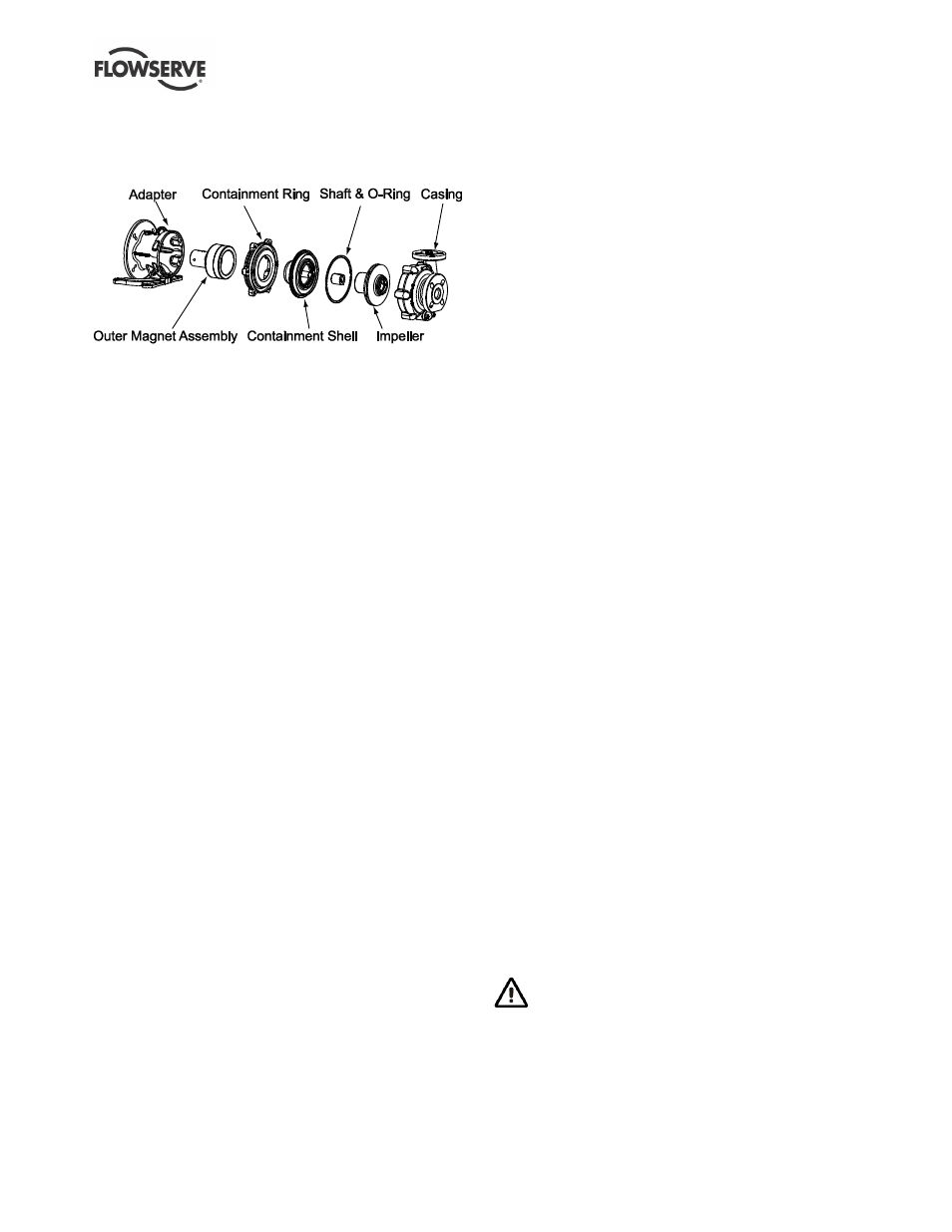
3.4 Design of major parts
3.4.1 Pump casing
Ductile iron armor with bonded ETFE lining.
The U-
MAG™ pump casing is designed with a
horizontal centerline end inlet and a top outlet.
For ease of maintenance, the pump is constructed so
that pipe connectors do not have to be disturbed
when internal maintenance is required (back pull out).
3.4.2 Impeller
Integrally molded one-piece impeller / inner rotor. The
impeller is fully shrouded (closed) with fully open
suction, and the inner rotor is fitted with Neodymium
Iron Boron (NdFeB) magnets.
3.4.3 Wetted Bearings System
The standard material for the bearing is carbon and
the shaft is alpha sintered silicon carbide (SiC). The
system is comprised of a shaft which is cantilever
mounted into the containment shell and a rotating
bushing mounted in the impeller. The impell
er’s wear
ring is carbon as standard and runs against the
casing thrust collar, which is SiC.
3.4.4 Containment Ring
One-piece ductile iron part aligns and supports the
containment shell to establish the pressure boundary
of the pump. Allows servicing of the motor without
opening the liquid end of the pump.
3.4.5 Outer Magnet Assembly
One-piece ductile iron housing fitted with Neodymium
Iron Boron (NdFeB) magnets. One common outer
rotor for each motor frame and a visual alignment
groove allows for ease of axial alignment.
3.4.6 Containment Shell and O-Ring
The containment shell is comprised of an aramid fiber
composite outer housing and an ETFE liner. The shell
includes a fully confined O-ring groove which
establishes the gasket interface with the casing.
3.4.7 Adapter
Mates pump to motor. Design allows the use of
multiple motors with one adapter.
3.4.8 Driver
The driver is normally an electric motor. Different drive
configurations may be fitted such as internal combustion
engines, turbines, hydraulic motors, and driving via
couplings, belts, gearboxes, drive shafts, etc.
3.4.9 Accessories
Accessories may be fitted when specified by the
customer
3.5 Performance and operating limits
This product has been selected to meet the
specifications of the purchase order. See section 1.5.
The following data is included as additional
information to help with your installation. It is typical,
and factors such as temperature and materials may
influence this data. If required, a definitive statement
for your particular application can be obtained from
Flowserve.
3.5.1 Operating limits
Normal maximum ambient temperature:
+40 ºC (104 ºF).
Normal minimum ambient temperature:
-20 ºC (-4 ºF).
Maximum pump speed: refer to the nameplate.
3.5.2 Pressure-Temperature Rating
The pump pressure and temperature limits are
included in the Figure 3-2. The standard U-MAG
TM
casing has a universal, slotted flange bolt pattern
which accommodates ANSI, ISO, and JIS piping
flange standards. Optional drilling arrangements
include ANSI Class 150, ISO PN 16, and JIS 10K.
Find the maximum allowable pressure for the
supplied pump, given the flange drilling pattern and
operating temperature.
The maximum discharge pressure must be less
than or equal to the P-T rating. Discharge pressure
may be approximated by adding the suction pressure
to the differential pressure developed by the pump.