Disassembly – Flowserve U-MAG INNOMAG User Manual
Page 24
U-MAG ENGLISH 26999990 10-14
Page 24 of 40
6.6 Disassembly
The preventative maintenance and disassembly
procedures are intended for use during standard field
inspection or service. The disassembly can take
place while the pump is piped up or in a maintenance
shop. If at all possible, it is recommended to perform
all repairs using the shop procedures to reduce the
risk of damage to the SiC parts.
Lock out driver power to prevent accidental
start-up that could result in serious personal injury.
Lock out and/or disconnect power.
Shut off all valves controlling flow to
and from the pump. Isolate the pump from the
system and relive any remaining system pressure.
Refer to Safety section before dismantling the
pump.
Before dismantling the pump for
overhaul, ensure genuine Flowserve INNOMAG®
replacement parts are available.
Refer to sectional drawings for part numbers and
identification. (See section 8, Parts lists and drawings.)
When operating with chargeable liquids with
conductivities of <10-8 S/m, inert gases (e.g. nitrogen)
must be used to flush the pump. Before removal of the
pump it is recommended to wait one hour to allow static
peak charges to be eliminated.
When handling hazardous and/or toxic
fluids, skin, eye and respiratory protection are required.
If pump is being drained, precautions must be taken to
prevent injury or environmental contamination.
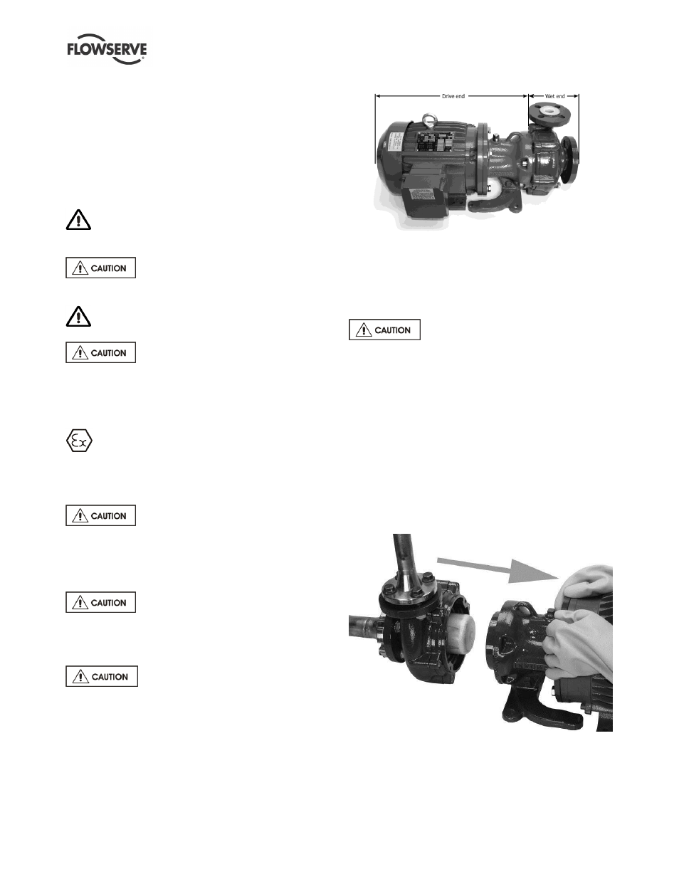
6.6.1 Drive / Wet End Separation
Flowserve INNOMAG® pumps contain
extremely strong magnets. The use of non-magnetic
tools and work surface is highly recommended. The
work area must be clean and free of any ferrous
particles.
Wet end and drive end separation
requires significant care. The magnetic coupling
between the impeller [2200] and outer drive [0230]
magnets is very strong. This process requires the
magnetic field between the outer drive and impeller to
be broken.
Figure 6-1
a)
Remove the bolt(s) connecting the support foot
[3134] to the base and any bolts connecting the
motor to the base.
b)
Remove the four adapter socket head cap
screws [6570.1] with an 8mm (5/16 in.) hex key.
Removing the close-coupled motor
requires significant care. The magnetic coupling
between the impeller and outer drive magnets is very
strong. The next step requires the magnetic field to be
broken. It is recommended to have a second person
with non-metallic spacers to place between the adapter
[1340] and containment ring [3830] to assist in
disassembly.
c)
Firmly hold the drive end (which includes the
adapter [1340], outer magnet assembly [0230] and
the motor) and with smooth, continuous force, pull
it away from the wet end. Pull the drive end back
at least 150 mm (6 in).
Figure 6-2
d)
Turn the drive end to the side to allow space for
disassembly of the wet end.