Wet end assembly, Drive end disassembly, 11 wet end assembly – Flowserve U-MAG INNOMAG User Manual
Page 29: 12 drive end disassembly
U-MAG ENGLISH 26999990 10-14
Page 29 of 40
k)
Repeat the proceeding four steps until you reach
the desired diameter.
l)
Chamfer the front and back outer edges of the
impeller [2200].
m)
Loosen the jaws and remove the Impeller [2200].
n)
Remove the trimming sleeve and trim any
remaining loose plastic with a hobby knife.
6.11 Wet End Assembly
6.11.1 Piped Up Assembly
Thoroughly clean all parts before assembly.
Make sure all parts are free of dirt, metallic particles,
etc.
With U-
MAG™ pumps, we highly
recommend following the shop assembly procedure
(Section 6.11.2) to minimize the chance of damaging
the SiC. Due to the brittle nature of SiC, all
assemblies must be handled with care to avoid
chipping or cracking.
a)
Align and slide the impeller [2200] onto the pump
shaft [2100] located inside the containment shell
[3500].
b)
Insert the assembled impeller [2200] and
containment shell [3500] into the containment
ring [3830]
c)
Insert the assembly as one piece into the casing
[1100].
Figure 6-16
d)
Align the containment ring [3830] so that the four
inner adapter [1340] bolt holes are on the right
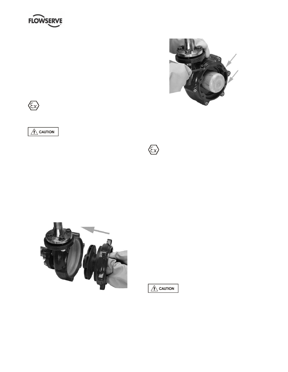
and left side of the pump (Figure 6-17).
e)
Insert and tighten (6) socket head cap screws
[6570.1] with lock washers [6541]. Torque the
socket head cap screws [6570.1] to 27 Nm (20
lbf
•ft).
Figure 6-17
f)
Align the drive end and push it straight in until it
meets the wet end.
g)
Tighten the four adapter socket head cap screws
and torque to 27 Nm (20 lbf
•ft).
6.11.2 In Shop Assembly
Thoroughly clean all parts before assembly.
Make sure all parts are free of dirt, metallic particles,
etc.
a)
With the casing [1100] face down, insert the
impeller [2200].
b)
When the impeller [2200] is in place, rotate it by
hand to make sure it spins freely.
c)
Align the shaft [2100] in the containment shell
[3500] with the bushing [3300] and lower the
containment shell [3500] into place.
d)
Place the containment ring [3830] over the
containment shell [3500] (refer to Figure 6-4).
e)
Align the containment ring [3830] so that the four
inner adapter [1340] bolt holes are on the right
and left side of the pump (refer to Figure 6-17).
f)
Insert six socket head cap screws [6570.1] with
lock washers [6541] into the six containment ring
[3830] bolt holes.
g)
Tighten the six socket head cap screws [6570.1]
with an 8 mm (5/16 in.) hex key and torque to 27
Nm (20 lbf
•ft).
6.12 Drive End Disassembly
The outer magnet assembly [0230]
contains very strong magnets. Use caution inserting
the jack screw. Under normal circumstances a visual
inspection and wiping clean the inside of the outer
magnet is sufficient.
6.12.1 NEMA Drive End Disassembly
a)
Remove the metal pipe plug [6569] from the top
of the adapter [1340].