Examination of parts, 7 examination of parts – Flowserve U-MAG INNOMAG User Manual
Page 25
U-MAG ENGLISH 26999990 10-14
Page 25 of 40
6.6.2 Wet End Disassembly
Skin, eye and respiratory protection are
required when handling hazardous and/or toxic fluids.
When draining, precautions must be taken to prevent
injury or environmental contamination.
Ensure suction and discharge valves
are completely closed.
Drain the pump and individually decontaminate
each component in accordance to all federal, state,
local and company environmental regulations.
Flowserve INNOMAG® pumps contain
extremely strong magnets. The use of non-magnetic
tools and work surface is highly recommended. The
work area must be clean and free of any ferrous
particles.
The following procedures assume the drive end and
wet end are separated. Refer to section 6.6.1 Drive /
Wet End Separation if the motor and pump are
connected.
6.6.2.1 Wet End Disassembly – Piped Up
a)
Remove the drain bolts [6570.1] (if the pump has
a drain). Drain the pump and individually
decontaminate each component in accordance to
all federal, state, local and company
environmental regulations.
b)
Loosen and remove (6) socket head cap screws
[6570.1] with an 8 mm (5/16 in.) hex key.
c)
Grasp the containment shell [3500] and pull the
assembly (including impeller [2200], containment
shell [3500], and containment ring [3830]) back in
a straight line until it is clear of the casing [1100].
Figure 6-3
d)
Remove the containment shell [3500] and
impeller [2200] from the containment ring [3800].
NOTE: This step is optional as removal of the
containment ring may be very difficult on pumps
that have been in service for long periods of time.
e)
Lift and remove the impeller [2200] from the
containment shell [3500].
6.6.2.2 Wet End Disassembly – in Shop
a)
Place a piece of cardboard or a shop towel on
the workspace to protect the plastic on the
suction flange.
b)
Lay the wet end face down on the suction flange
in the work area.
c)
Loosen and remove the (6) socket head cap
screws [6570.1] on the containment ring [3830]
with an 8 mm (5/16 in.) hex key.
d)
Slightly rotate the containment ring to make it
easier to grip.
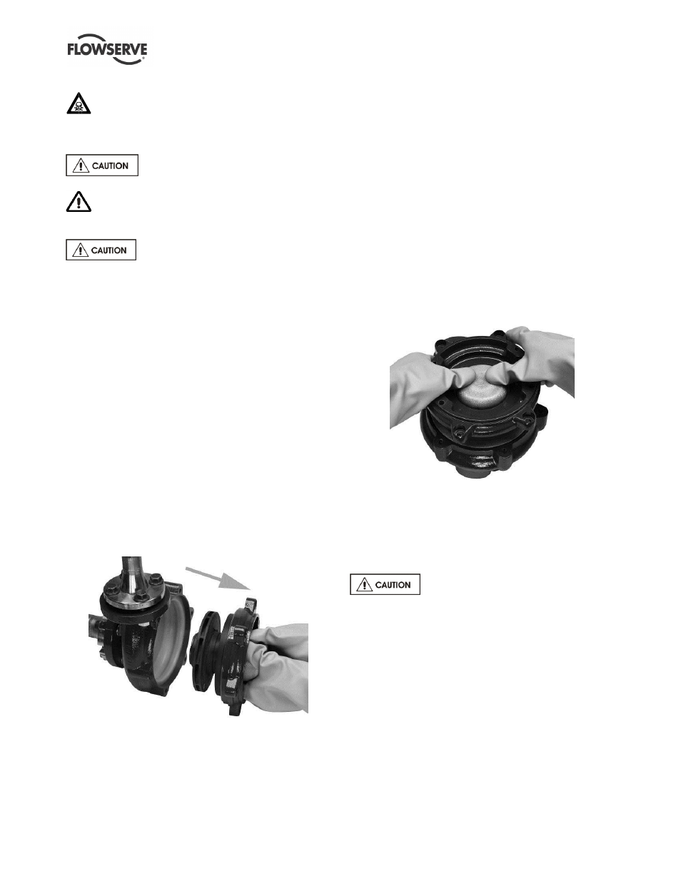
e)
Lift the containment ring [3830] with your fingers
while holding down the containment shell [3500]
with your thumbs.
Figure 6-4
f)
Lift the containment shell straight [3500] up from
the impeller [2200].
g)
Carefully lift and remove the impeller [2200] from
the casing [1100].
6.7 Examination of parts
Used parts must be inspected before
assembly to ensure the pump will subsequently run
properly. In particular, fault diagnosis is essential to
enhance pump and plant reliability.
6.7.1 Casing [1100] lining
Inspect the casing [1100] lining for any abrasion,
cracks or delamination. Casing [1100] replacement is
necessary if lining is breached. Minor scratches or
cuts less than 0.1 mm (0.040 in.) depth are
acceptable.
6.7.2 Silicon Carbide (SiC)
When inspecting the pump internals check all Silicon
Carbide (SiC) parts for cracks, chips and scoring
marks. Minor chips less than 0.5 mm (0.020 in.) are
acceptable. If replacement of any part is required,