Piping – Flowserve U-MAG INNOMAG User Manual
Page 17
U-MAG ENGLISH 26999990 10-14
Page 17 of 40
b) Inspect for any damage that would impede
proper installation or future use of the baseplate.
c) Confirm baseplate hole pattern for proper
mounting bolt installation.
d) Lower the baseplate carefully onto mounting
bolts. Caution: Must adhere to proper transport
and lifting procedures.
e) Level the baseplate using shims and/or wedges.
Use machinist’s levels to maintain a flat and level
surface.
f) Max difference across length 3.2 mm (0.125 in.)
g) Max difference across width 1.5 mm (0.059 in.)
h) Secure baseplate using mounting bolts to prevent
unwanted movement during operation. Torque
bolts to appropriate company standards and
practices.
i)
Perform final inspection to verify that baseplate is
securely mounted, level, and ready to be used.
4.5 Piping
Protective covers are fitted to both the
suction and discharge flanges of the casing and must
be removed prior to connecting the pump to any pipes.
4.5.1 Suction and discharge piping
Never use pump as a support for piping.
Ensure piping and fittings are flushed
before use.
Ensure piping for hazardous liquids is arranged
to allow pump flushing before removal of the pump.
Take into account the available NPSH which must be
higher than the required NPSH of the pump.
All piping must be independently supported, accurately
aligned and preferably connected to the pump by a
short length of flexible piping. The pump should not
have to support the weight of the pipe or compensate
for misalignment. It should be possible to install suction
and discharge bolts through mating flanges without
pulling or prying either of the flanges. All piping must be
tight. Pumps may air-bind if air is allowed to leak into
the piping. If the pump flange(s) have tapped holes,
select flange fasteners with thread engagement at least
equal to the fastener diameter but that do not bottom
out in the tapped holes before the joint is tight.
The following is the recommended procedure for
attaching piping to the U-
MAG™ pump (see section 6.5
for torque values)
Check the surface of both flanges (pump/pipe) to
ensure they are clean, flat, and without defects
Lubricate the fasteners
Hand tighten all of the fasteners in a crisscross
pattern
The fasteners should be torqued in increments
–
based a crisscross pattern
See torque chart in Section 6.5
o The first increment should be 75% of full torque
o The second increment should be at the full torque
o Verify that the torque value of the 1
st
fastener is
still at the full torque value. Re-torque all
fasteners after 24 hours or after the first thermal
cycle.
Re-torque all fasteners at least annually
4.5.2 Suction piping
To avoid NPSH and suction problems, suction piping
must be at least as large as the pump suction
connection. Never use pipe or fittings on the suction
that are smaller in diameter than the pump suction
size.
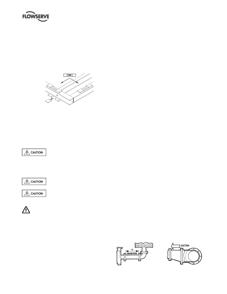
Figure 4-5 illustrates the ideal piping configuration
with a minimum of 10 pipe diameters between the
source and the pump suction. In most cases,
horizontal reducers should be eccentric and mounted
with the flat side up as shown in Figure 4-6 with a
maximum of one pipe size reduction. Never mount
eccentric reducers with the flat side down.
Horizontally mounted concentric reducers should not
be used if there is any possibility of entrained air in
the process fluid. Vertically mounted concentric
reducers are acceptable. In applications where the
fluid is completely de-aerated and free of any vapour
or suspended solids, concentric reducers are
preferable to eccentric reducers.
Figure 4-5 Figure 4-6