Flowserve U-MAG INNOMAG User Manual
Page 28
U-MAG ENGLISH 26999990 10-14
Page 28 of 40
Figure 6-12
6.10.2 Bushing Installation
a)
Line up the bushing’s [3300] locking groove with
the molded key inside the impeller [2200].
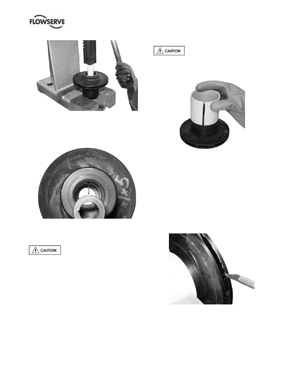
Figure 6-13
b)
Insert the bushing [3300], making sure to
maintain alignment while inserting into the arbor
press.
Make sure the bushing removal tool is
perfectly centered to prevent damaging the inside of
the impeller [2200]. We recommend placing a shop
towel under the impeller to prevent damage to the
impeller front wear ring [3043].
c)
Center the PVC pipe on the bushing and press
the bushing [3300] into place. When properly
inserted, the bushing [3300] should be flush with
the bottom ledge of the impeller [2200].
6.10.3 Front Rotating Wear Ring [3043]
The U-MAG
TM
impeller wear ring [3043] is not user
replaceable. Contact your Flowserve representative
for repair or replacement.
6.10.4 Impeller Trimming
Place the trimming sleeve (Part #
TLG-2033-FM) over the impeller [2200] to protect it
from damage.
Figure 6-14
a)
Using a calipers, measure the current diameter of
the impeller [2200].
b)
Insert the impeller [2200] into the lathe and
tighten the jaws.
c)
Set the trim 6 mm (1/4 in.) less than the current
diameter. If you have never trimmed an impeller
[2200] before, then we recommend only cutting 3
mm (1/8 in.) at a time.
d)
Trim the first pass at a slow speed.
e)
Use the hobby knife to clean off the loose plastic
on the impeller [2200] in order to get an accurate
measurement.
Figure 6-15
f)
Check the diameter again with the caliper.
g)
Set the lathe for 6 mm (1/4 in.) less than the
current diameter measurement.
h)
Trim this layer at a slow speed.
i)
Clean off any loose plastic that would interfere
with your diameter measurements.
j)
Use the caliper to measure the current diameter.