Drive end assembly, 13 drive end assembly – Flowserve U-MAG INNOMAG User Manual
Page 30
U-MAG ENGLISH 26999990 10-14
Page 30 of 40
b)
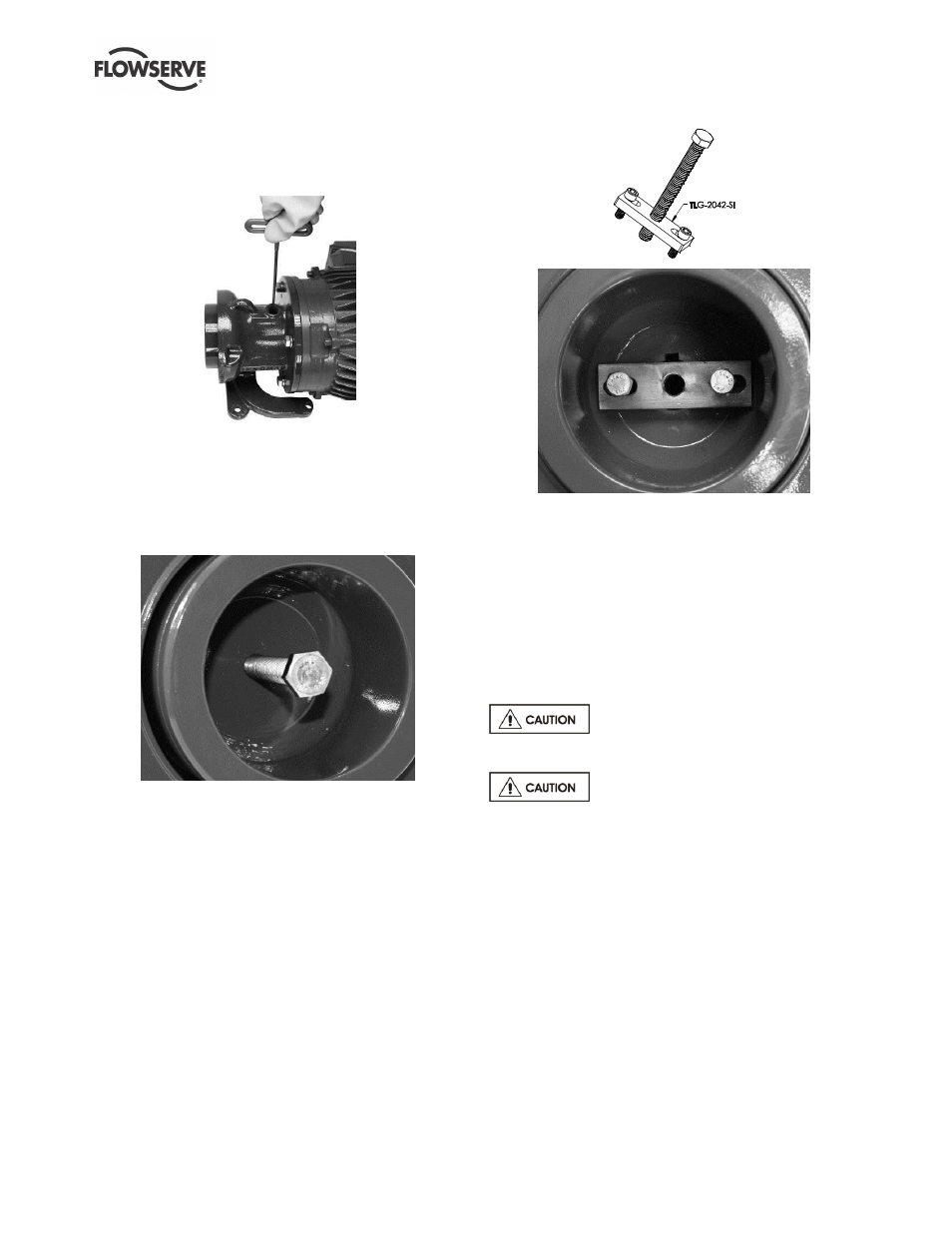
Locate and loosen the (2) set screws on the on
the outer magnet assembly [0230] with a 3/16 in.
T-Handle allen wrench.
Figure 6-18
c)
Insert a 1/2 in. - 13 x 6+ in. jack bolt into the
center of the NEMA outer magnet assembly
[0230].
d)
Using a 3/4 in. socket spanner (wrench), tighten
the jack bolt to free the outer magnet assembly.
Figure 6-19
e)
Carefully remove the outer magnet assembly
[0230].
f)
Remove (4) screws from the adapter [1340].
g)
Remove the adapter [1340] from the motor.
6.12.2 IEC Drive End Disassembly
a)
Remove the metal pipe plug [6569] from the top
of the adapter [1340].
b)
Locate and loosen the (2) set screws on the on
the outer magnet assembly [0230] with a 5mm T-
Handle allen wrench as shown in Figure 6-18.
c)
Attach the jack screw plate [TLG-2042-SI] with
(2) M8 x 1.25 x 30 mm screws into the treaded
holes inside the IEC outer magnet assembly
[0230].
Figure 6-20
d)
Insert a M12 x 1.75 x 100+ mm jack bolt into the
center of the jack screw plate [TLG-2042-SI] and
tighten the center jack bolt to free the outer
magnet assembly [0230].
e)
Carefully remove the outer magnet assembly
[0230].
f)
Remove (4) screws from the adapter [1340].
g)
Remove the adapter [1340] from the motor.
6.13 Drive End Assembly
The Outer Magnet Assembly [0230]
contains very strong magnets.
Do not use blunt force on front face of
the outer magnet assembly. If difficult, verify motor
shaft meets manufacture’s tolerances and is free of
burrs.
6.13.1 NEMA Drive End Assembly
a)
Align the (4) holes on the support foot [3134] with
the (4) holes on the adapter [1340].
b)
Insert and tighten the (4) riser screws.
c)
Line up the adapter [1340] holes with the
threaded holes on the motor.
d)
Insert (4) bolts [6570.1] with lock washers [6541]
and tighten until no gap is present between the
adapter [1340] and the motor mounting face.
e)
Note the placement of the set screws on the outer
magnet assembly [0230] in relation to the drive
pins before installation.
Set screw (A) will be