Wet / drive end assembly, 14 wet / drive end assembly – Flowserve U-MAG INNOMAG User Manual
Page 32
U-MAG ENGLISH 26999990 10-14
Page 32 of 40
d)
Once properly configured, align the (4) holes on
the riser block with the (4) holes on the adapter
[1340].
e)
Align the (4) holes on the support foot [3134] with
the (4) holes on the riser block.
f)
Insert and tighten the (4) riser screws.
g)
Align the bolt holes on the motor with the threaded
holes on the adapter [1340] or adapter plate (if
installed).
h)
Insert tighten the (4) bolts [6570.1] with lock
washers [6541] through the motor flange into the
adapter [1340] or adapter plate, if equipped.
i)
Remove plug [6569] from the adapter [1340].
j)
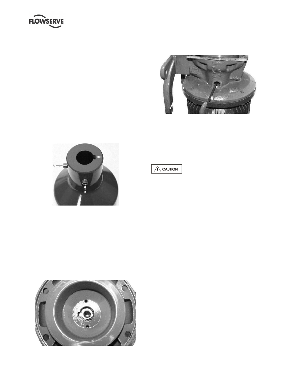
Note the placement of the set screws on the outer
magnet assembly [0230] in relation to the key
notch before installation. Set screw (A) will be
directly across from the key notch. Set screw (B)
will be perpendicular to the key notch.
Figure 6-27
k)
Make sure a key is installed in the motor shaft
keyway. Align the key groove on the outer magnet
assembly [0230] with the key on the motor shaft
and install.
l)
Use a ruler, straight edge or visually align the
groove on the outer magnet assembly [0230] with
the outer edge of the adapter [1340].
m)
Look inside the outer magnet assembly [0230] and
rotate it until the motor key points away from the
plug hole. Set screw (A) should now be visible
through the hole on the adapter [1340].
Figure 6-28
n)
Tighten set screw (A) with the 5 mm T-handle
allen wrench.
Figure 6-29
o)
Rotate the outer magnet assembly [0230] by 90°
counterclockwise to locate and tighten set screw
(B).
p)
Replace the metal plug [6569] on the adapter
[1340] and drive end assembly is complete.
6.14 Wet / Drive End Assembly
Assembling the close-coupled motor
requires significant care. The magnetic coupling
between the impeller and outer drive magnets is very
strong. It is recommended to have a second person
with non-metallic spacers to place between the adapter
[1340] and containment ring [3830] to assist in
assembly.
6.14.1 Piped Up Assembly
a)
Line up the drive end with the wet end, ensuring
proper motor and adapter height relative to the
wet end.
b)
Carefully slide the motor forward until it engages
with the containment ring [3830] without a gap.
c)
Insert and tighten the (4) socket head cap screws
to hold the adapter to the wet end. Torque the
socket head cap screws to 27 Nm (20 lbf
•ft).
d)
Insert and tighten any support foot [3134] and
motor foot screws to secure the assembly to the
base.
6.14.2 In-Shop Assembly
a)
Holding the wet end by the suction and/or
discharge flange, carefully insert the wet end into
the drive end in a straight line as shown in Figure
6-30.
b)
Insert and tighten the (4) socket head cap screws
to hold the adapter to the wet end. Torque the
socket head cap screws to 27 Nm (20 lbf
•ft).