Grouting – Flowserve U-MAG INNOMAG User Manual
Page 16
U-MAG ENGLISH 26999990 10-14
Page 16 of 40
e)
Assemble the stilt bolt up through hole in the
bottom plate and hold in place.
f)
Assemble the lock washer [3] and nut [2] on the
stilt bolt. Tighten the nut down on the lock
washer.
g)
After all four stilts have been assembled,
position the baseplate in place, over the floor
cups [4] under each stilt location, and lower the
baseplate to the floor.
h)
Level and make final height adjustments to the
suction and discharge pipe by first loosening the
top nuts and turning the bottom nuts to raise or
lower the baseplate.
i)
Tighten the top and bottom nuts at the lock
washer [3] first then tighten the other nuts.
j)
It should be noted that the connecting pipelines
must be individually supported, and that the stilt
mounted baseplate is not intended to support
total static pipe load.
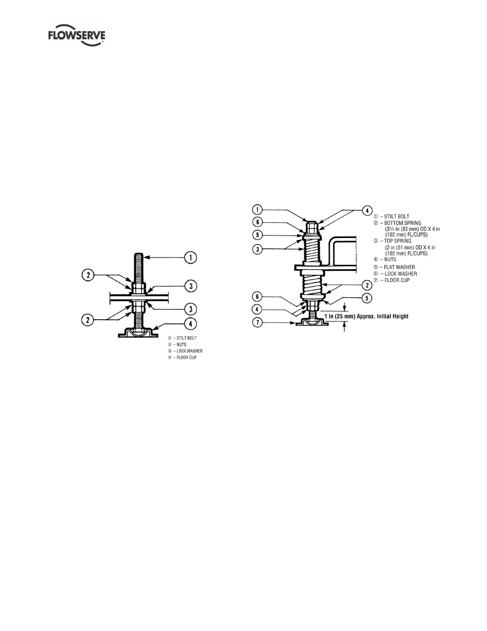
Figure 4-3
4.3.3.2 Stilt/spring mounted baseplate assembly
instructions
Refer to Figure 4-4.
a)
Raise or block up baseplate/pump above the
floor to allow for the assembly of the stilts.
b)
Set the bottom nuts [4] above the stilt bolt head
[1]. This allows for 51 mm (2 in.) upward
movement for the final height adjustment of the
suction/discharge flange.
c)
Assemble the lock washer [6] flat washer [5] and
bottom spring/cup assembly [2] down over the
stilt bolt [1].
d)
Assemble the stilt bolt/bottom spring up through
hole in the bottom plate and hold in place.
e)
Assemble top spring/cup assembly [3] down
over stilt bolt.
f)
Assemble flat washer [5], lock washer [6] and
nuts [4] on the stilt bolt.
g)
Tighten down top nuts, compressing the top
spring approximately 13 mm (0.5 in.). Additional
compression may be required to stabilize the
baseplate.
h)
After all four stilts have been assembled,
position the baseplate in place, over the floor
cups [7] under each stilt location, and lower the
baseplate down to the floor.
i)
Level and make final height adjustments to the
suction and discharge pipe by first loosening the
top nuts, and turning the bottom nuts to raise or
lower the baseplate.
j)
Recompress the top spring to the compression
established in step g, and lock the nuts in place.
k)
It should be noted that the connecting pipelines
must be individually supported, and that the
spring mounted baseplate is not intended to
support total static pipe loads.
Figure 4-4
The remaining steps are as listed for new grouted
baseplates.
4.4 Grouting
Where applicable, grout in the foundation bolts.
Foundation bolts should only be fully tightened when
the grout has cured.
After adding pipework connections and rechecking the
pump alignment, the baseplate should then be grouted
in accordance with good engineering practice.
Fabricated steel, folded steel and cast iron baseplates
can be filled with grout. Polycrete baseplates cannot be
grouted in the same way, see their User Instructions
71569284 (E) for installation and use. If in any doubt,
please contact your nearest service center for advice.
Grouting provides solid contact between the pump unit
and foundation prevents lateral movement of vibrating
equipment and dampens resonant vibrations.
4.4.1 Baseplate Inspection
a) Completely clean the underside of baseplate.