2 nomenclature, 3 design of major parts, 1 pump casing – Flowserve ESP2 User Manual
Page 11: 2 impeller, 3 shaft, 4 pump bearings and lubrication, 5 bearing housing, 6 shaft seal, 7 driver, 8 accessories
ESP2 USER INSTRUCTIONS ENGLISH PCN-(71569292) 4-12
Page 11 of 64
3.2 Nomenclature
The pump size will be engraved on the nameplate
typically as below:
6 X 4 X 10
• “6” = nominal suction port size (in.)
• “4” = Nominal discharge port size (in.)
• Nominal maximum impeller diameter. “10” = 10 in.
• Actual impeller size
“9.5” = 9 ½ in. diameter; “8.13” = 8
⅛ in;
”7.75” = 7 ¾ in
3.3 Design of major parts
3.3.1 Pump casing
Casings are either a single or double volute design with
a centerline discharge.
3.3.2 Impeller
The impeller is an open design and is threaded to the
end of the shaft.
3.3.3 Shaft
Solid shafting is supported on plain bearings with a
thrust bearing located above the sump level.
3.3.4 Pump bearings and lubrication
Grease lubricated double row angular contact ball
bearings are fitted as standard for the external thrust
bearings. The plain bearings that support the shaft
against radial loads can be lubricated either by
external flush, product, or grease (see Fig. 3-4).
3.3.5 Bearing housing
The external bearing housing holds the thrust
bearing and has lip seals to prevent ingress of
contaminates to the bearing grease.
3.3.6 Shaft seal
There is no shaft seal required near the impeller
since the pump is submerged. Only a small amount
of pressurized fluid escapes through controlled leak
paths from the backside of the impeller. Packing or
a mechanical seal can be fitted above the sump level
to provide vapor proof or pressurized options for the
application.
3.3.7 Driver
The driver is normally a vertical electric motor.
3.3.8 Accessories
Accessories may be fitted when specified by the
customer.
3.4 Performance and operation limits
This product has been selected to meet the
specification of your purchase order. See section 1.5.
The following data is included as additional information
to help with your installation. It is typical, and factors
such as liquid being pumped, temperature, material of
construction, and seal type may influence this data. If
required, a definitive statement for your application can
be obtained from Flowserve.
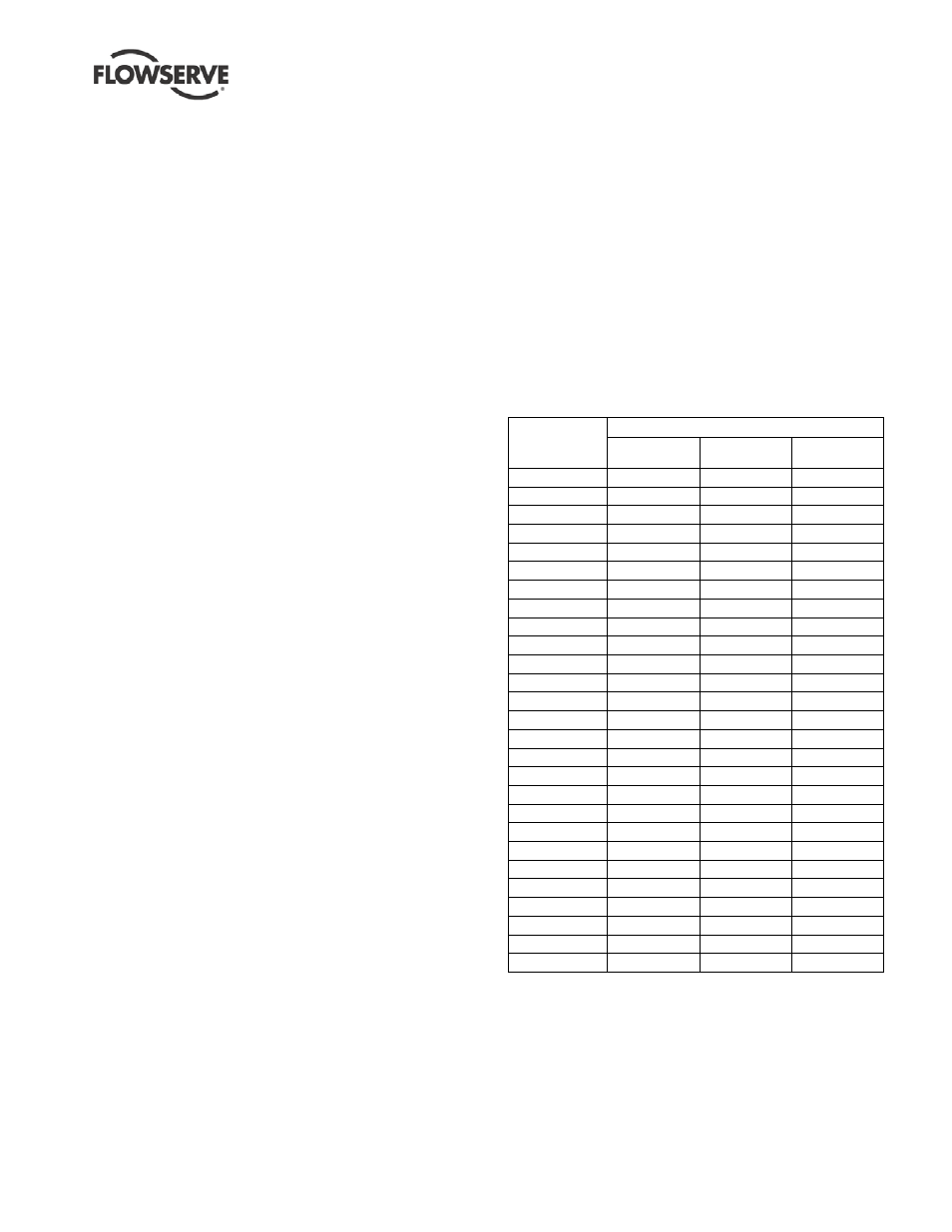
3.4.1 Minimum continuous flow
The minimum continuous flow (MCF) is based on a
percentage of the best efficiency point (BEP). Figure
3-2 identifies the MCF for all ESP pump models.
FIGURE 3-2: Minimum continuous flow
Pump size
MCF % of BEP
3500/2900
r/min
1750/1450
r/min
1180/960
r/min
Group 1
1.5x1x6
10
10
10
3x1.5x6
10
10
10
3x2x6K
10
10
10
1.5x1x8
10
10
10
3x1.5x8
n.a.
10
10
3x2x8
n.a.
10
10
Group 2
3x1.5x8
10
10
10
3x2x8
10
10
10
4x3x8
25
10
10
4x3x8L
n.a.
25
10
2x1x10
n.a.
25
10
3x1.5x10
n.a.
25
10
3x2x10
n.a.
25
10
4x3x10
n.a.
25
10
4x3x10L
n.a.
25
10
6x4x10
n.a.
25
10
3x1.5x13
n.a.
25
10
3x2x13
n.a.
25
10
4x3x13
n.a.
25
10
Group 3
6x4x13
n.a.
25
10
8x6x13
n.a.
25
10
10x8x13
n.a.
25
10
8x6x15
n.a.
n.a.
25
10x8x15
n.a.
n.a.
25