6 piping, 1 discharge piping, 2 suction piping – Flowserve ESP2 User Manual
Page 17
ESP2 USER INSTRUCTIONS ENGLISH PCN-(71569292) 4-12
Page 17 of 64
d)
Locate the coupling and source of electrical
power but DO NOT ASSEMBLE THE
COUPLING AT THIS TIME.
e)
Connect the motor terminals to the leads from
the starter panel. Make sure the motor shaft
and/or coupling is not touching any part of the
pump shaft or pump half coupling. Rotate the
motor shaft by hand to make sure it is free to
rotate when energized.
Never check driver rotation unless the
pump and driver are disconnected and
physically separated. Failure to follow this
instruction can result in serious damage to the
pump and driver if rotation is in the wrong
direction.
f)
Jog the motor and check for proper rotation
which should be clockwise when looking
down on top of the motor. If rotation is wrong,
interchange any two motor connections on
three-phase motors. On single-phase motors,
follow the motor manufacturer’s instructions. After
changing the connections, again check the rotation
to ensure that the direction is correct.
g)
Disconnect and lockout the power supply to the
driver.
h)
The coupling can now be fully installed and
join the driver and pump shafts together (see
section 5.4.2).
i)
Install the coupling guarding (see section
5.5).
4.6 Piping
4.6.1 Discharge piping
All piping must be independently supported,
accurately aligned and preferably connected to the
pump by a short length of flexible piping. The pump
should not have to support the weight of the pipe. It
should be possible to install discharge bolts through
mating flanges without pulling or prying either of the
flanges. All piping must be tight.
Protective covers are fitted to both the
suction and discharge flanges of the casing and must
be removed prior to connecting the pump to any
pipes.
a)
Use discharge piping one size larger than the
pump discharge.
b)
Discharge piping should be well supported
and connected to the pump such that no strain
or weight of the piping is carried by the pump.
c)
Check pump shaft for freedom of rotation by
hand to make sure any discharge piping strain
is not causing binding.
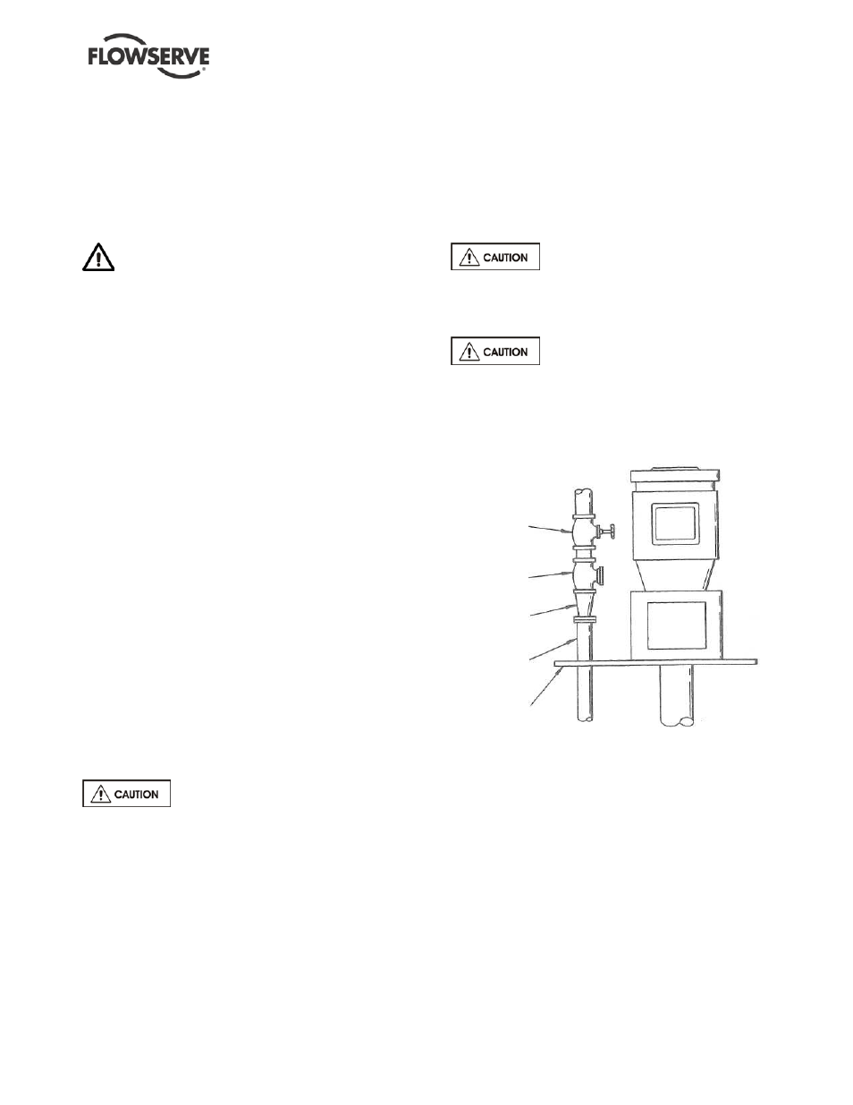
d)
After the pump discharge, the increaser
should be the first item in the discharge line,
followed by the check valve and gate valve,
respectively. See Figure 4-1.
e)
It is recommended that pressure indicating
devices be installed before and after the
valves in the discharge line to verify the pump
is not being run dry and that the discharge
valves are not closed.
The check valve is required to
prevent back-flow through the pump on shut-down.
This flow could cause the impeller to unscrew from
the shaft and should be avoided.
When fluid velocity in the pipe is
high, for example, 3 m/s (10 ft/sec) or higher, a
rapidly closing discharge valve can cause a
damaging pressure surge. A dampening
arrangement should be provided in the piping.
FIGURE 4-1
4.6.2 Suction piping
ESP pumps typically only have strainers attached to
the suction flange of the pump casing. An option for
an extension from the suction flange is available and
is called a tailpipe (see section 8 for cross-sectional
drawing). A tailpipe is useful for applications where
there is adequate NPSH at the lowest sump level but
the discharge pressure is critical and must be
maintained at a maximum value compared to using a
longer column and shaft.
GATE
VALVE
CHECK
VALVE
CONCENTRIC
INCREASER
PUMP.
DISCHARGE
MOUNTING,
PLATE