2 critical measurements and tolerances, 3 parameters that should be checked by users, 1 shaft – Flowserve ESP2 User Manual
Page 41: 2 bearings, 3 impeller balancing, 4 vibration analysis, Figure 6-6
ESP2 USER INSTRUCTIONS ENGLISH PCN-(71569292) 4-12
Page 41 of 64
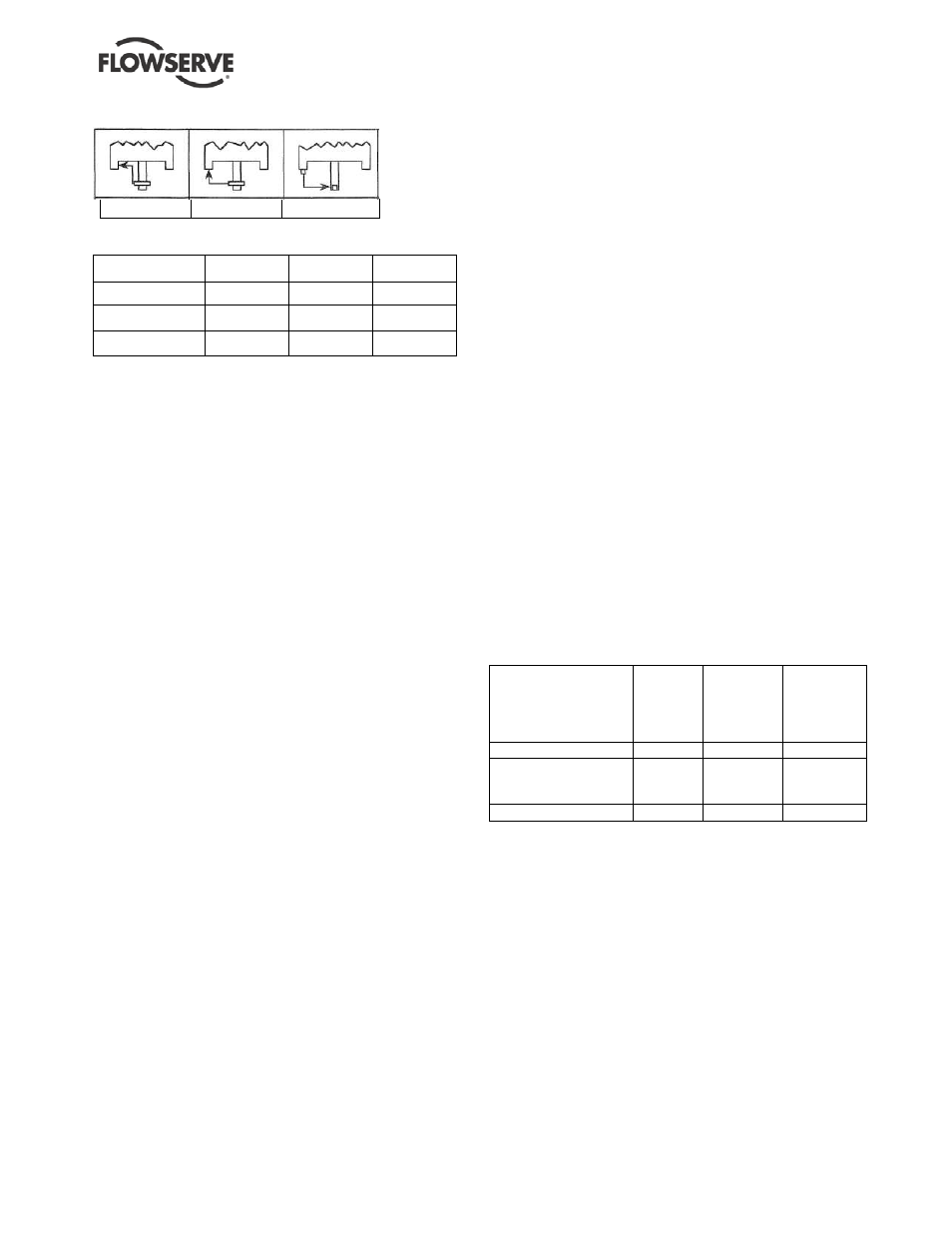
FIGURE 6-5 Motor tolerances
A
B
C
T.I.R. Dimensions -- mm (in.)
Frame Size
A
B
C
143TCV-256TCV
0.10 (0.004)
0.10 (0.004)
0.05 (0.002)
284TCV-286TCV
0.10 (0.004)
0.10 (0.004)
0.08 (0.003)
324TCV-445TCV
0.18 (0.007)
0.18 (0.007)
0.08 (0.003)
h)
Inspect inside of bearings (3020.1-.2) in the
adapter (1340.1) and intermediate bearing
holder(s) (3250). Check for cracks, uneven or
excessive wear, scoring or heat discoloration,
and corrosion. Bearings should be replaced as
described in Section 6.7.2.
6.8.2 Critical measurements and tolerances
To maximize reliability of pumps, it is important that
certain parameters and dimensions are measured
and maintained within specified tolerances. It is
important that all parts be checked. Any parts that do
not conform to the specifications should be replaced
with new Flowserve parts.
6.8.3 Parameters that should be checked by
users
Flowserve recommends that the user check the
measurements and tolerances in Figure 6-6
whenever pump maintenance is performed. Each of
these measurements is described in more detail on
the following pages.
6.8.3.1 Shaft
Replace if grooved, pitted or worn, especially where
the shaft rides in the sleeve bearings.
6.8.3.2 Bearings
It is recommended that rolling element bearings not
be used after removal from the shaft.
6.8.3.3 Impeller balancing
Shaft whip is deflection where the centerline of the
impeller is moving around the true axis of the pump.
It is not caused by hydraulic force but rather by an
imbalance with the rotating element. Shaft whip is
very hard on the mechanical seal because the faces
must flex with each revolution in order to maintain
contact.
To minimize shaft whip it is imperative that the
impeller is balanced. All impellers manufactured by
Flowserve are balanced after they are trimmed. If for
any reason, a customer trims an impeller, it must be
re-balanced. See note 1 under Figure 6-19 regarding
acceptance criteria.
6.8.3.4 Vibration analysis
Vibration analysis is a type of condition monitoring
where a pump’s vibration “signature” is monitored on
a regular, periodic basis. The primary goal of
vibration analysis is extension on MTBPM. By using
this tool Flowserve can often determine not only the
existence of a problem before it becomes serious, but
also the root cause and possible solution.
Modern vibration analysis equipment not only detects
if a vibration problem exists, but can also suggest the
cause of the problem. On a centrifugal pump, these
causes can include the following: unbalance,
misalignment, defective bearings, resonance,
hydraulic forces, cavitation and recirculation. Once
identified, the problem can be corrected, leading to
increased MTBPM for the pump.
Flowserve strongly urges customers to work with an
equipment supplier or consultant to establish an on-
going vibration analysis program. See section 5.8.7
for guidance on vibration monitoring.resfdb
FIGURE 6-6
Topic
ASME
B73.1M
standard
mm (in.)
Suggested
by major
seal
vendors
mm (in.)
Suggested
and/or
provided by
Flowserve
mm (in.)
Impeller Balance
See note 1
Bearing housing
Diameter (ID) tolerance
at bearings
n/s
0.013 (0.0005)
Shaft endplay
n/s
0.05 (0.002)
0.05 (0.002)
n/s = not specified.
1. The maximum values of acceptable unbalance are:
1500 r/min: 40 g
∙mm/kg (1800 r/min: 0.021 oz-in/lb) of mass.
2900 rpm: 20 g
∙mm/kg (3600 rpm: 0.011 oz-in/lb) of mass.
Flowserve performs a single plane spin balance on most
impellers. The following impellers are exceptions: 10X8-13,
10X8-15. On these Flowserve performs a two plane dynamic
balance, as required by the ASME B73.1M standard. All
balancing, whether single or two plane, is performed to the ISO
1940 Grade 6.3 tolerance criteria.
2. The ASME B73.1M standard does not specify a recommended
level of alignment. Flowserve recommends that the pump and
motor shafts be aligned to within 0.05 mm (0.002 in.) parallel FIM
(full indicator movement) and 0.0005 mm/mm (0.0005 in./in.)
angular FIM. Closer alignment will extend MTBPM.