5 fastener torques, 7 disassembly, 1 removing pump from pit – Flowserve ESP2 User Manual
Page 38: 2 pump disassembly
ESP2 USER INSTRUCTIONS ENGLISH PCN-(71569292) 4-12
Page 38 of 64
6.5 Fastener torques
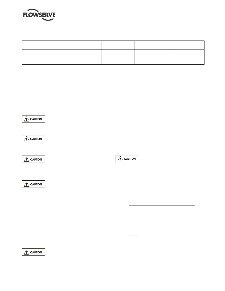
FIGURE 6-2: Recommended maximum bolt torques
Item
Description
Group 1
non-lubricated
Group 2
non-lubricated
Group 3
non-lubricated
[6580.2] Mechanical seal gland studs/nuts, with gasket
⅜ in. – 16 Nm (12 lbf•ft) ⅜ in. – 16 Nm (12 lbf•ft)
½ in. – 41 Nm (30 lbf•ft)
[6580.2] Mechanical seal gland studs/nuts, with O-ring
⅜ in. – 27 Nm (20 lbf•ft) ⅜ in. – 27 Nm (20 lbf•ft)
½ in. – 54 Nm (40 lbf•ft)
[6580.1] Casing studs/nuts and all other bolting
½ in. – 41 Nm (30 lbf•ft)
½ in. – 41 Nm (30 lbf•ft)
⅝ in. – 81 Nm (60 lbf•ft)
¾ in. – 136 Nm (100 lbf•ft)
⅞ in. – 217 Nm (160 lbf•ft)
Notes:
1. For lubricated or PTFE-coated threads, use 75% of the values given.
2. Gasket joint torque values are for unfilled PTFE gaskets. Other gasket materials may require additional torque to seal.
Exceeding metal joint torque values is not recommended.
6.6 Setting impeller clearance and
impeller replacement
A new impeller o-ring [4610] must be installed
whenever the impeller has been removed from the
shaft. Impeller clearance settings may be found in
section 5.3. Impeller balancing instruction may be
found in section 6.8.
Do not adjust the impeller clearance with the seal set.
Doing so may result in seal leakage and/or damage.
The impeller could have sharp edges,
which could cause an injury. It is very important to
wear heavy gloves when handling an impeller.
It is recommended that two people
install a Group 3 impeller. The weight of a Group 3
impeller greatly increases the chance of thread
damage and subsequent lock-up concerns.
Do not attempt to tighten the impeller
on the shaft by hitting the impeller with a hammer or
any other object or by inserting a pry bar between the
impeller vanes. Serious damage to the impeller may
result from such actions.
Install the impeller [2200] by screwing it onto the shaft
(use heavy gloves) until it firmly seats against the
shaft shoulder.
6.7 Disassembly
Use extreme care in removing and dismantling pump.
Refer to pump assembly drawings for part
nomenclature (see Section 8).
Depending on the product being
pumped, the pump should be washed down and
decontaminated before any work is done on it.
6.7.1 Removing pump from pit
a)
Close control valve in discharge line.
b)
Lock out power supply to driver.
c)
Disconnect all electrical connections.
d)
Disconnect any external auxiliary piping
connections.
e)
Disconnect discharge piping from pump.
f)
Disconnect coupling guard and coupling halves.
g)
Disconnect driver and remove.
h)
Unbolt pump mounting plate (6110) and lift
pump (see Sections 2.3 and 4.4) from pit. Let
the pump drain thoroughly before removing
pump completely. Remove casing drain, if
supplied.
i)
Remove liquid level controls (if any).
j)
Lift the pump (see Sections 2.3 and 4.4) out of
the pit and lay pump horizontally on supports.
For units that are welded, the welded
sections should not be disassembled unless the parts
need to be replaced.
6.7.2 Pump disassembly
a)
Pump discharge pipe removal
• For Groups 1 and 2 and 6x4x13: unscrew the
flange (1245.2), locknut (3712), and loosen
the lower locknut. Then the upper discharge
pipe (1360) can be unscrewed.
• For Group 3 pumps (except the 6x4x13):
unscrew the flange (1245.2). These pumps
are furnished with the discharge pipe bolted
to the mounting plate by a flange (1245.3)
and four screws (6570.11). Remove the
screws holding the flange to the mounting
plate (6110).
• Both: the discharge pipe (1360) can then be
removed by unbolting the elbow (1371) from
the discharge of the casing (1100) and
pulling the discharge pipe out from the under
side of the mounting plate (6110).