Figure 5-1, Figure 5-2, 2 packing the stuffing box – Flowserve ESP2 User Manual
Page 28: Figure 5-3, Packing information
ESP2 USER INSTRUCTIONS ENGLISH PCN-(71569292) 4-12
Page 28 of 64
A variety of seal piping plans designed to suit certain
pumping conditions and liquids are available.
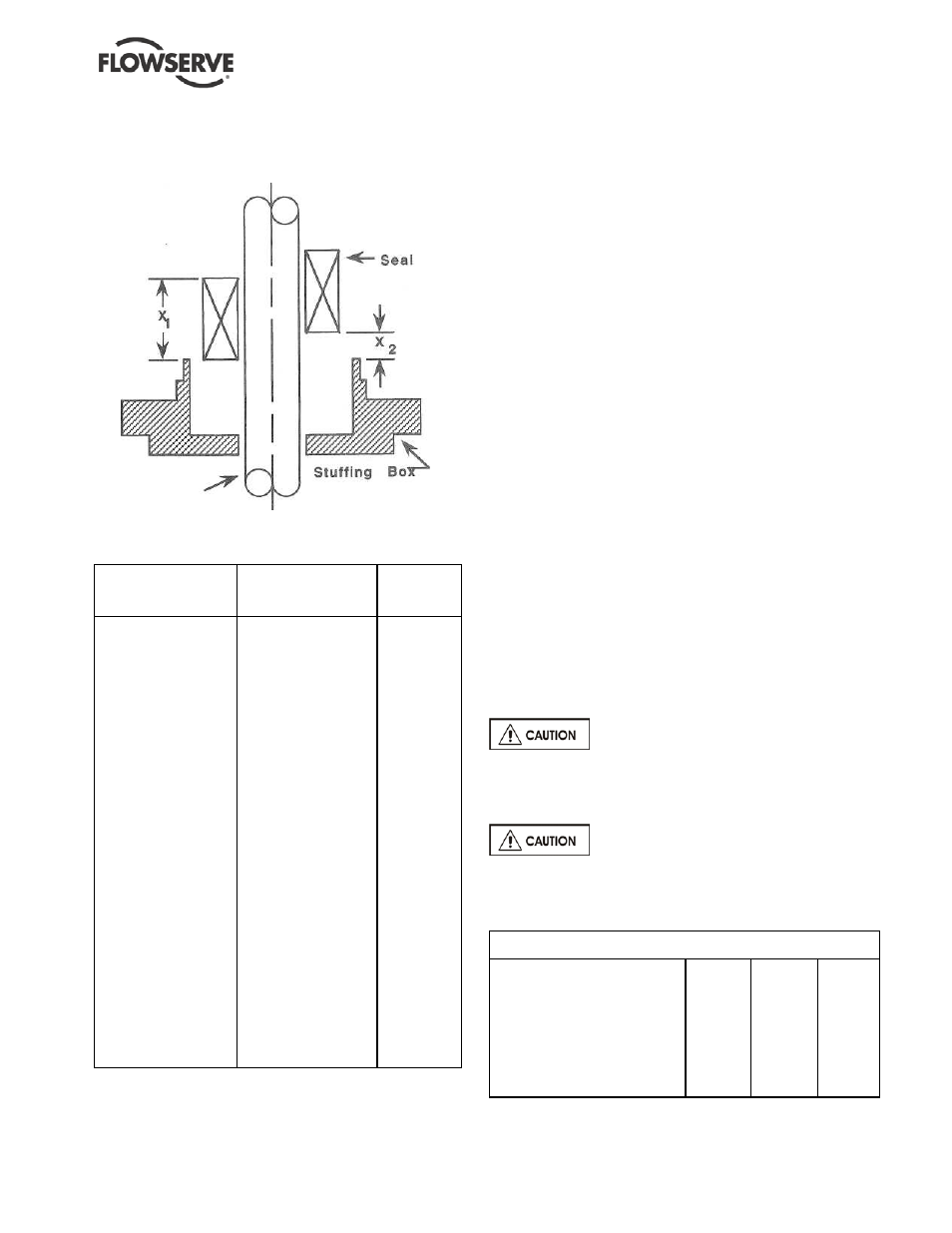
FIGURE 5-1
FIGURE 5-2
SEAL
X1
SEAL
X2
SEALS
mm
mm
REQUIRING
In.
In.
NO SETTING
Durametallic:
Durametallic:
John Crane:
Group 1 RAC
52.3
Group 1 PSS
0.0
T-1 double
2.06
Group 2 PSS
0.0
1100
Group 2 RAC
52.3
Group 3 PSS
0.0
Cartridge T-1B
2.06
Chesterton:
88
Group 3 RAC
71.4
Group 1 221
1.6
88S
2.81
0.0625
28LD
Group 1 VO
73.2
Group 2 221
1.6
1215
2.88
0.0625
2215
Group 2 VO
76.2
Group 3 221
1.6
Flexibox:
3.00
0.0625
FFET
Group 3 VO
John Crane:
Sealol:
John Crane:
Group 1 8B2
44.5
611
Group 2 37FS
50
1.750
623
1.968
Group 2 8B2
44.5
Borg-Warner:
Group 3 37FS
50
1.750
Uniseal I
1.968
Group 3 8B2
44.5
Uniseal II
1.750
Durametallic:
X-100
X-200
P-50
CRO double
Chesterton:
123
155
241
255
5.1.2.2 Packing the stuffing box
Inspect the stuffing box to see if it contains packing.
The pump normally leaves the factory with the
stuffing box unpacked, and it must be packed before
the pump is put into service. A complete set of
packing cut to proper lengths is included with other
loose parts in a box attached to the pump skid. The
stuffing box should be packed in the following
manner:
a)
Remove (or raise out of the way) the stuffing box
gland.
b)
Carefully clean the stuffing box (with a lint free
doth) clear of any scale build up and foreign
matter which may have entered during shipment
or storage.
c)
In packing the stuffing box put in one ring at a
time, pushing it well into place. Two rings of
packing must be installed, and then the seal
cage, then succeeding rings of packing until the
box is filled. THE JOINTS OF SUCCEEDING
RINGS MUST BE STAGGERED. See Figure 5.3
for additional packing information.
d)
After the last ring of packing is in place, draw up
the nuts on the gland (4120.1) evenly finger
tight, then tighten nuts an extra 1/4 turn to initially
set the packing. A slight amount of leakage
through the gland is necessary for proper
lubrication. Packing glands must never be
tightened to the point where leakage from the
packing is stopped.
e)
Preserve any left over packing for future use.
After the packing has been compressed under
operating conditions, there may be enough room
to allow another ring to be inserted.
There is a tapped hole leading into
the stuffing box for the purpose of sealing the
packing with liquid or grease. When the packing is
compressed, the seal cage must be in line with this
passage.
Shutting off leakage flow from the
packing will result in burned packing and scored
shafts.
FIGURE 5-3
Packing Information
Group 1
Group 2
Group 3
Packing size, square (inches)
0.31
0.31
0.38
Packing arrangement
2-C-3
2-C-3
2-C-3
Seal Cage width
0.50
0.75
0.50
Shaft Diameter
1.125
1.500
1375
1.123
1498
1873
Shaft