Flowserve ESP2 User Manual
Page 39
ESP2 USER INSTRUCTIONS ENGLISH PCN-(71569292) 4-12
Page 39 of 64
b)
Remove bearing lubrication lines (3840.1).
c)
Unbolt and remove the pump casing (1100).
The strainer (6531) does not need to be
removed from the casing unless it is to be
cleaned or replaced.
d)
Remove the impeller (2200) by unscrewing it
counter-clockwise (looking in at the vanes) while
holding the drive coupling with a strap wrench.
Do not attempt to use a crowbar as a lever to
unscrew the impeller as damage to the vanes
may result. Use a strap wrench or a piece of
wood as a mallet. The impeller threads are
sealed by an O-ring (4610) which should then be
replaced.
e)
Removing the thrust bearing:
• Pumps without Vapor Proof or Pressurized
Construction: remove the thrust bearing by
first unbolting the support head (3160). For
groups 1 and 2 the support head will be
disconnected from the mounting plate (6110)
and for group 3 the support head will be
disconnected from the upper column
(1341.1).
For Group 3 pumps, any columns still
attached to the pump at this time must be firmly
supported. The upper column will disconnect from
the mounting plate at the same time that the support
head is disconnected.
• Now remove the thrust bearing holder (3110)
and the thrust bearing assembly (3031, 3712)
by unscrewing the sleeve (3712) from the
shaft (2100).
• Pumps with Vapor Proof or Pressurized
Construction: first remove the support head
(3160) from the bearing bracket (3130). Next
remove the bearing body (3110) and the
thrust bearing assembly (3031, 3712) by
unscrewing the sleeve (3712) from the shaft
(2100). For groups 1 and 2 the bearing
bracket will be disconnected from the
mounting plate (6110) and for group 3 the
bearing bracket will be disconnected from the
upper column (1341.1).
For Group 3 pumps, any columns still
attached to the pump at this time must be firmly
supported. The upper column will disconnect from
the mounting plate at the same time that the support
head is disconnected.
Before the next procedure, be sure to
cover the shaft threads with a Teflon tape for
protection when sliding parts off the shaft to prevent
the shaft threads from being damaged or causing
damage to other parts.
f)
Unbolt the gland and carefully slide it off the end
of the shaft. If the pump contains a seal, VERY
CAREFULLY, slide the seal off of the shaft. If
the pump contains packing remove the packing
at this time.
g)
Now the stuffing box can be unbolted and
removed gently from the shaft.
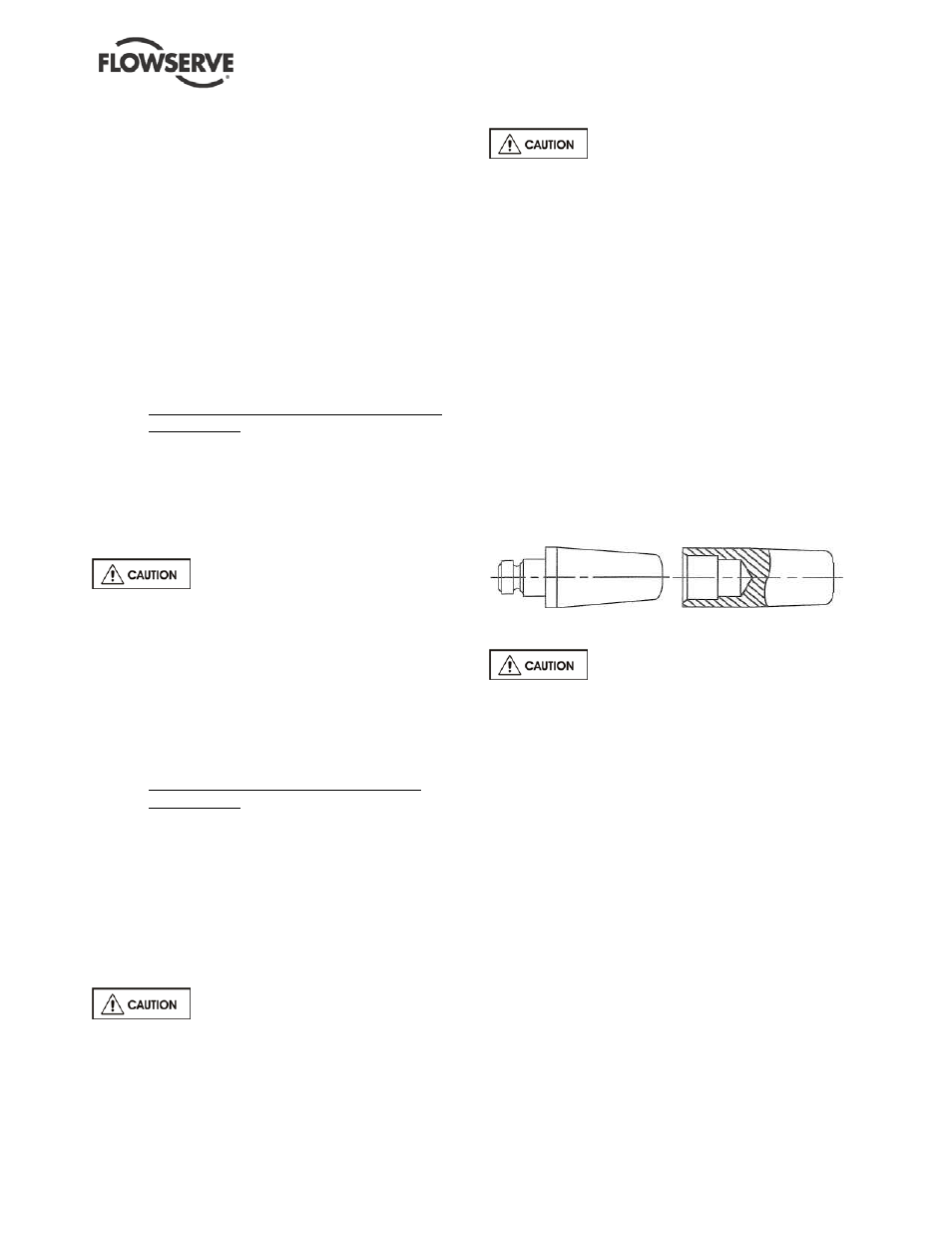
h)
A shaft-bullet (See Figure 6-3) is recommended,
but not required, for the next step. If a shaft
bullet is to be used, attach the bullet in place of
the impeller (2200). Remove the shaft (2100)
from the remainder of the pump.
FIGURE 6.3 Shaft
bullets
Group 3 (Excluding 6x4x13)
Always remove the shaft by pulling it
out through the mounting plate end as shaft threads
may cause damage to the lineshaft bearings if pulled
through the casing end.
i)
Unbolt and remove the adapter (1340.1).
j)
Unbolt and remove the columns (1341.2) and
the bearing holders (3250) until the upper
column is reached (1341.1).
k)
The shaft bearings should not be removed from
their housings unless they are to be replaced.
Table 6.1 shows a listing of allowable bearing
tolerances. If these tolerances are exceeded,
either the bearings (3020.1-.2), shaft (2100), or
bearing holder (3250) should be replaced.
l)
Intermediate shaft bearings (3020.1) can be
pressed or driven out of their bearing holder
(3250) when replacing.
m) The adapter bearing (3020.2) may be removed
by pressing or driving the bearing sleeve from
the upper flange (column side) out through the
lower end (casing side) of the adapter (1340.1)
taking the seal ring (2500) with it.
Groups 1, 2, and 6x4x13