4 direction of rotation, 1 rotation check, 2 coupling installation – Flowserve ESP2 User Manual
Page 32: 5 guarding, 6 priming and auxiliary supplies, 7 starting the pump
ESP2 USER INSTRUCTIONS ENGLISH PCN-(71569292) 4-12
Page 32 of 64
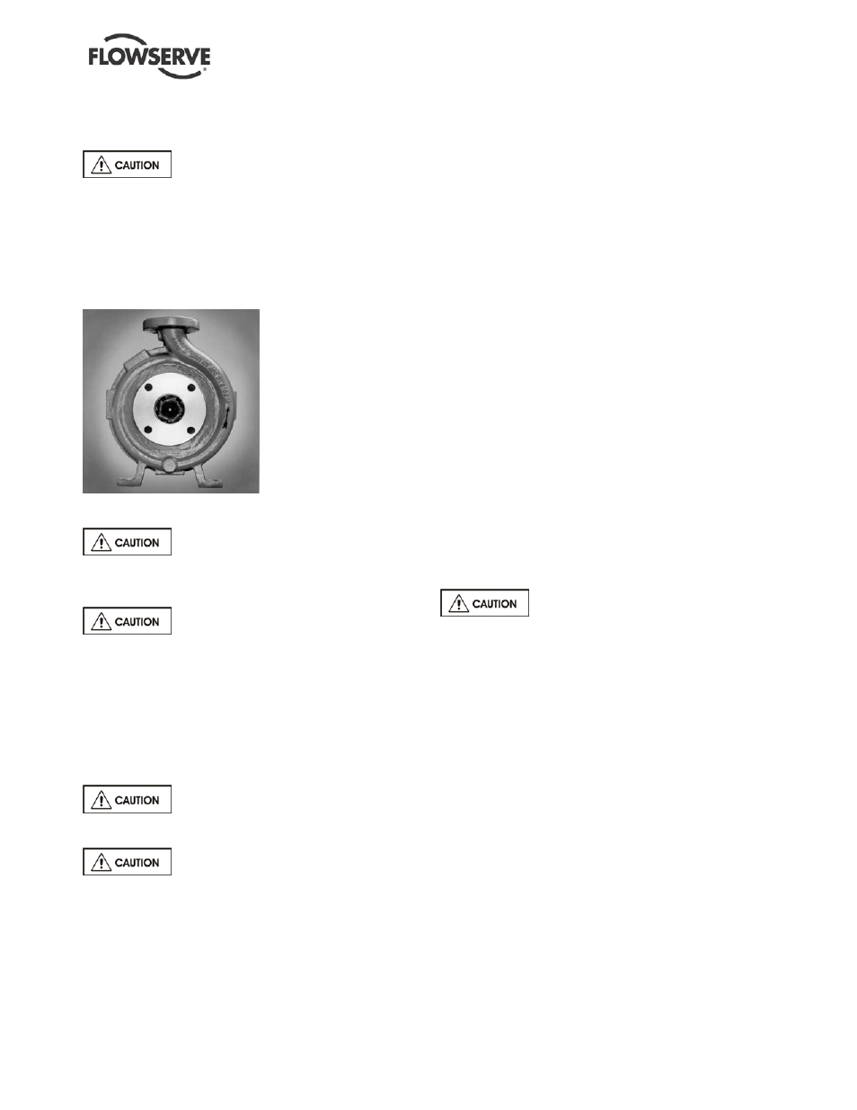
5.4 Direction of rotation
5.4.1 Rotation check
It is absolutely essential that the
rotation of the motor be checked before connecting
the shaft coupling. Incorrect rotation of the pump, for
even a short time, can dislodge and damage the
impeller, casing, shaft and shaft seal. All ESP pumps
turn clockwise as viewed from the motor end. A
direction arrow is cast on the front of the casing and
support head [3160] as shown in Figure 5-7. Make
sure the motor rotates in the same direction.
FIGURE 5-7
5.4.2 Coupling installation
Turn off the driver power and lock it
out so that the driver cannot be started during the
coupling assembly.
The coupling should be installed as
advised by the coupling manufacturer. Pumps are
shipped without the spacer installed. If the spacer
has been installed to facilitate alignment, then it must
be removed prior to checking rotation. Remove all
protective material from the coupling and shaft before
installing the coupling.
5.5 Guarding
Power must never be applied to the
driver when the coupling guard is not installed.
The pump must not be operated
without an approved coupling guard in place. Failure
to observe this warning could result in injury to
operating personnel.
Flowserve coupling guards are safety devices intended
to protect workers from inherent dangers of the rotating
pump shaft, motor shaft and coupling.
It is intended to prevent entry of hands, fingers or other
body parts into a point of hazard by reaching through,
over, under or around the guard. No standard coupling
guard provides complete protection from a
disintegrating coupling. Flowserve cannot guarantee
their guards will completely contain an exploding
coupling.
For ESP pumps, install the coupling guard with the
connecting hardware.
5.6 Priming and auxiliary supplies
The fluid moving components (casing, impeller, and
adaptor) of ESP pumps should be submerged during
normal operation, so priming is not an issue.
Depending on the bearing lubrication options and the
shaft sealing options, some auxiliary supply lines may
need to be brought to the ESP pump. Check to see if
any other connections need to be made to pump,
such as injection water to stuffing box for seal or
packing lubrication (when furnished) and make the
required connections.
5.7 Starting the pump
All steps within section 4.0 “INSTALLATION” and
section 5.1 "PRE-COMMISSION PROCEDURE"
must be complete before initiating the pump starting
procedure.
To avoid pump damage or injury to
operating personnel during start-up and operation:
•
DO NOT operate the pump outside of design
parameters.
•
DO NOT run with a closed discharge for more than
one minute.
•
DO NOT operate with safety devices (i.e. coupling
guard) removed.
•
DO NOT run the pump dry.
After all pre-starting checks have been performed, the
pump is ready to start. Observe the following procedure
to put the pump into operation:
a)
Rotate the pump shaft by hand through at least one
complete revolution to see that there is no rub or
bind.
b)
Check the discharge piping and destination of the
flow.
c)
Check the sump liquid level. Liquid level must be
sufficient enough to engulf the casing and adapter
d)
Close, or leave open very slightly, the control valve in
the discharge line.
e)
If external flush-lubricated bearings are used, turn on
water supply to the bearings.