4 grouting – Flowserve MF User Manual
Page 17
MF USER INSTRUCTIONS ENGLISH 71569191 12/04
Page 17 of 50
®
b) As a minimum, baseplate level shall be set with a
master level or a precision machinist level. Level
should checked before beginning the plate
leveling process by checking level repeatability
when reversing 180 degrees. All base plate level
measurements are taken on the equipment-
mounting surface.
c) The equipment baseplate mounting surface are
to be leveled longitudinally and transversely to
within 200
µ
m/m (0.002 in./ft) for API-610 pumps
and to within 400
µ
m/m (0.005 in./ft) for general
purpose & other pumps.
d) Baseplate level is achieved by adjusting the
jackscrews and then snugging the anchor bolt
nut to hold the base plate in place.
If leveling nuts are used on the
foundation bolts to level the base, they must be
backed off as far as possible prior to grouting the
base in place. Always shim near the foundation
bolts, back off the leveling nuts, and tighten the
foundation bolts. To do otherwise will significantly
lower the structural natural frequency and result in
separation of the base from the grout.
4.4 Grouting
The pump and motor must be aligned
on the base prior to grouting the base in place (see
alignment). Improper grouting will negate the factory
pre-alignment. Grouting provides solid contact
between the equipment and foundation that prevents
lateral movement of the equipment and may also
help in dampening resonant vibrations.
The purpose of grouting is to prevent lateral shifting
of the equipment supports and not to take up
irregularities in the foundation. Only non-shrinking
grout should be used.
4.4.1 Recommended procedure for grouting:
a) Build a wooden form around the outside of the
baseplate to contain the grout. In some cases
the form is placed tightly against the lower edge
of the base and in other cases it is placed a slight
distance from the edge of the baseplate.
b) Saturate the top of the rough concrete foundation
with water, if required before grouting. Add grout
until the entire area within the baseplate is filled,
including the motor pedestal and the space
between the foundation bolt and pipe sleeve. A
stiff wire should be used to work the grout and
release any air pockets.
c) The drain pocket should be plugged before
grouting. Grout in the drain pocket area should
be poured to the drain pocket level and sloped to
the pocket (see 4.4.1.1).
The motor pedestal
should be led to the level shown on the elevation
drawing.
d) The grout is poured and cured slowly to prevent
cracking. The grout is set for a minimum of
about 48 hours. The grout should be allowed to
cure at least 72 hours before it is dynamically
loaded.
e) If desired, the grout surface in the drain pocket
area may be treated or painted to resist oil and
grease.
f) Drainage will flow through the grout encased pipe
from the drain pocket to the pipe coupling on the
baseplate. The drainage can be picked up at this
point and directed to a convenient disposal area.
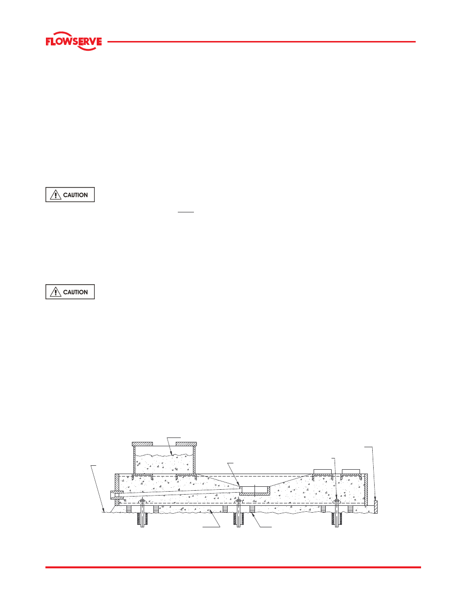
4.4.1.1 Grouting method
FILL MOTOR PEDESTAL
WITH GROUT TO LEVEL
SHOWN ON ELEVATION
DRAWING
SHIM NEAR
FOUNDATION BOLTS
SLOPE GROUT TO
DRAIN POCKET
ANCHOR BOLT
FORM FOR
GROUTING
FOUNDATION
GROUT