Flowserve MF User Manual
Page 37
MF USER INSTRUCTIONS ENGLISH 71569191 12/04
Page 37 of 50
®
b) Check that the face of the stuffing box is square
with the shaft sleeve to within the Seal
Manufacture's tolerances. This surface must be
smooth and flat to ensure good sealing between
the mechanical seal gland and stuffing box face.
c) Mount the rotating assembly in the pump and
adjust the wearing ring gap. Remove the rotating
assembly from the pump and scribe a line on the
shaft sleeve to mark the location of the stuffing
box face in relation to the shaft sleeve. Remove
the stuffing box head.
The wearing gap must be set before the
mechanical seal is mounted since setting the gap
relocates the shaft sleeve in relation to the stuffing
box head by as much as 6.35 mm (0.25 in.). If the
wearing gap is reset, then the mechanical seal must
be remounted. Check that the sleeve is free of pits,
burrs or sharp edges to prevent cutting or improper
sealing of the rotating "O" rings. The sleeve surface
must be highly polished to the dimensions and
tolerances indicated on the seal installation drawing
6.1.9.3 Installing the seal
Refer to the manufacturer's instructions for seal
installation.
6.1.9.4 Before starting the unit
Check and make certain that the gland flushing line
(and return line if a double seal) is clean, open and
free of any obstruction that may interfere with
circulation of clear flushing liquid for the seal.
Before start up bleed all air from the seal cavity. This
is necessary to ensure a clean liquid environment for
effective seal operation
6.1.10 Re-lubrication
Lubricant and bearing temperature analysis can be
useful in optimizing lubricant change intervals. In
general the following is recommended.
6.1.10.1 Oil lubrication
Maintaining the correct oil level is very
important. If a sight glass has been fitted then
regular checks should be made to ensure the level is
maintained at the center of the glass window.
Refer to section 5. for methods of oil fill, oil grade
recommendations and for the schedule and
temperature limits.
6.1.10.2 Grease lubrication
See section 5.2.6.1
for recommended
grease types. Re-grease via grease nipples. See
section 5.2.3.
a) It is important not to under or over grease the
bearings as this will lead to over heating and
premature failure. Grease lubricated bearing
housings have grease nipples fitted in the
bearing covers.
b) Connect grease gun to the nipple.
c) Press grease into the bearing housing until the
first signs of it appear in the gap between the
housing and shaft, then stop greasing.
d) The maximum allowable operating temperatures
for anti-friction bearings will vary from unit to unit,
depending on ambient and fluid temperature.
The rise above ambient should not normally
exceed 55
°
C (131
°
F) or a combined maximum
of 95
°
C (204
°
F).
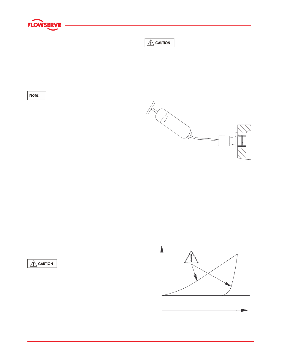
e) A continuously rising temperature or an abrupt
temperature rise indicates a problem. If these
symptoms occur, stop the pump immediately and
investigate the cause
.
TIME
TE
M
P
E
R
A
TU
R
E