5 fastener torques, 6 renewal clearances, 7 disassembly – Flowserve MF User Manual
Page 40
MF USER INSTRUCTIONS ENGLISH 71569191 12/04
Page 40 of 50
®
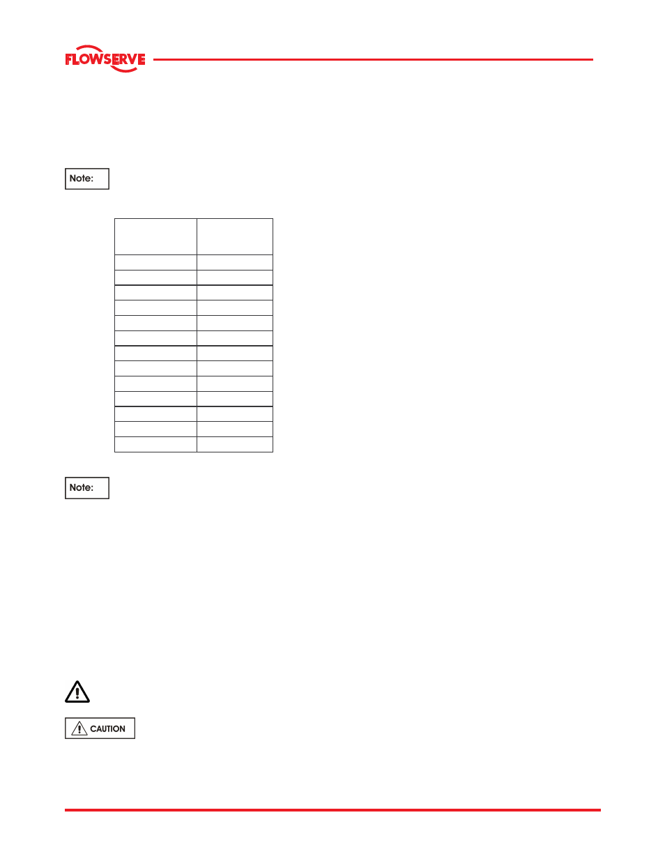
6.5 Fastener torques
The following table is provided as a guide for the
proper assembly of Grade (SAE) 2 fasteners.
Torques are for lubricated threads. Lubricate the
fastener and tapped hole threads and the underside
of the bolt heads and nuts before assembly.
DO NOT lubricate threads that require the
application of Loctite thread locking compound.
Bolt Size
mm (in.)
Torque
Nm (lb·ft)
M 6 (1/4)
8 (6)
M 8 (5/16)
16 (12)
M 10 (3/8)
28.5 (21)
M 12 (7/16)
47.5 (35)
M 14 (1/2)
70 (50)
M 16 (5/8)
135 (100)
M 20 (3/4)
235 (175)
M 24 (7/8)
205 (150)
M 27 (1)
305 (225)
M 30 (1-1/8)
435 (320)
M 33**
(1-1/4)
610 (450)
M 36 (1-3/8)
800 (590)
M 39**
(1-1/2)
1070 (790)
**
Non-preferred size
For assembly of a joint always finger
tighten all nuts or bolts first. Then cross-tighten
evenly in about three equal steps to develop final
torque values.
6.6 Renewal clearances
As wear takes place between the impeller and casing
ring the overall efficiency of the pump set will
decrease. To maintain optimum efficiency it is
recommended that rings are replaced and the
impeller refurbished. The clearance dimensions
depends on pump size. Contact Flowserve
representative for service advise.
6.7 Disassembly
Refer to section 1.6,
Safety
, before dismantling
the pump.
Before dismantling the pump for
overhaul, ensure genuine Flowserve replacement
parts are available.
Refer to sectional drawings purchased for part
reference numbers (also see section 8.0 ).
6.7.1 Preliminary to dismantling
a) Isolate motor and lock off electrical supply in
accordance with local regulations.
b) Isolate suction and discharge valves.
c) Remove coupling guards and disconnect the
coupling halves.
d) Drain pump casing. Remove any auxiliary piping
if applicable.
e) For convenience at re-assembly, lay out all parts
in the order in which they are removed.
f) Protect all machined faces against metal-to-metal
contact and corrosion.
g) Proceed as follows referencing the pump
Sectional Drawing provided in Section 8.
6.7.2 Pump dismantling procedure
Care must be exercised in the dismantling operation.
Close the suction and discharge valves and drain
liquid from the casing. For convenience at re-
assembly, lay out all parts in the order in which they
are removed. Protect all machined faces against
metal to metal contact and corrosion. Proceed as
follows referencing the pump Sectional Drawing.
For MF pumps, disconnect the coupling and remove
motor; unless provided with spacer coupling in which
case only remove the spacer portion. Also, unbolt the
stuffing box head support (bearing frame support on
frame 7A) from the base.
a) Unbolt the stuffing box head from the casing.
b) Draw out rotor assembly with stuffing box head,
bearing housing, etc. Care must be exercised in
slinging and handling the unit.
c) Remove impeller screw and impeller cover plate.
It may be necessary to heat the impeller screw to
400 degrees F as it is mounted using Loctite
thread locker (#271 or equal).
d) Remove impeller and impeller key.
e) Remove the packing gland. If the pump is
equipped with a mechanical seal unbolt the gland.
f) Unbolt and remove stuffing box head from bearing
frame.
g) Packing and seal cage halves may be removed
from stuffing box head at this time.
h) Remove the mechanical seal if so equipped.
i) On horizontal pumps, the stuffing box head
support (bearing frame support on frame 7A) may
be removed at this time.
j) Remove deflector (lower outboard seal ring on
frames 4T, 5T, 6A and 7A).